
Unit installation


22
VW T5
Validity
Foreword
These installation instructions apply to VW T5 vehicles with a Gasoline and Diesel engine (van with
partition wall) from model year 2004 and later, assuming technical modifications to the vehicle do not
affect installation, any liability claims excluded.
Vehicles and equipment variants, which are not listed in these installation instructions, have not been
tested. However, installation according to these installation instructions may be possible. Depending
on the version and the equipment variants of the vehicle, changes may be necessary relative to these
"installation instructions" during installation and must be adjusted accordingly.
However, where this is the case the stipulations in the "installation instructions" and "operating and
maintenance instructions" for the Air Top 2000 ST should be observed.
The installation location of heater controls and the routing of the air ducting parts must be coordinated
with the final customer prior to installation!
WARNING!
Original load-bearing components of the vehicle and/or component used for crash safety may not be
modified for the hot air and recirculating air ducting!
General Instructions
Installation should be carried out according to the general, standard rules of technology. Unless spec-
ified otherwise, fasten hoses, lines and wiring harnesses to original vehicle lines and wiring harnesses
using cable ties.
Sharp edges should be fitted with edge protectors (split-open plastic hose).
Spray unfinished body areas, e.g. drilled holes, with anti-corrosion wax (Tectyl 100K, Order No.
111329).
Manufacturer Model Type EG-BE No./ABE
Volkswagen Transporter T5 L148
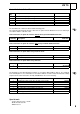
Validity 2
Heater Units 3
Foreword 3
General Instructions 3
Special tools 3
Explanatory Notes on the Document 4
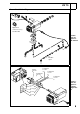
General Installation Diagram 5
Preliminary Work 6
Heater Unit Installation Location 6
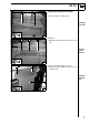
Preparing Installation Location 7
Preparing Heater Unit 8
Installing Heater Unit 9
Combustion Air 10
Fuel Connection 11
Metering Pump 12
Fuel Removal on Vehicles
without Additional or Auxiliary Heater 13
Fuel Removal on Vehicles
with Additional or Auxiliary Heater 14
Exhaust System 15
Optional Exhaust Muffler 15
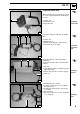
Optional Hot Air System 16
Optional Recirculating Air 19
Electrical Connections 20
Optional Combination Timer 20
External Temperature Sensor 20
Remote Option (Telestart) 21
Fault Code Deactivation 26
Final Work 27
Operating Instructions for End Customer 28
Template for Fuel Sender 29
Template for Fuel Standpipe 30
Table of Contents