Coolant Heater Thermo 90 Thermo 90 S Workshop Manual Webasto Thermosystems Inc. North America 3333 John Conley Drive Lapeer, MI 48446 Phone (810) 245-2400 Toll-free (800) HEATER-1 Fax (810) 664-7720 Technical Assistance Hotline USA: (800) 555-4518 Canada: (800) 667-8900 Rev. 03/2000 907400 www.webasto.
THERMO 90 / 90 S TABLE OF CONTENTS Table of Contents 1. Introduction 1.1 Scope and Purpose . . . . . . . . . . . . . . . . . . . . . . . . . . . . . . . . . . . . . . . . . . . . . . . . . . . . 1.2 Meaning of Warnings, Cautions and Notes . . . . . . . . . . . . . . . . . . . . . . . . . . . . . . . . . . 1.3 Additional Documentation to be used . . . . . . . . . . . . . . . . . . . . . . . . . . . . . . . . . . . . . . . 1.4 General Safety Regulations and Information . . . . . . . . . . . . . . . . .
TABLE OF 5.4.1 5.5 Reading and Removing Error Codes Stored in Memory using the PC Diagnostics Kit P.N. 92542C . . . . . . . . . . . . . . . . . . . . . . . . . . . . . . . . . . . 5-3 Visual Inspection for Assessment of Burner Condition . . . . . . . . . . . . . . . . . . . . . . . . . . 5-4 5.5.1 5.5.2 5.5.3 5.5.4 6. THERMO 90 / 90 S CONTENTS Burner Housing . . . . . . . . . . . . . Rear Wall with Metal Evaporator Combustion Chamber . . . . . . . . Burner Assembly . . . . . . . . . . . . . . . .
THERMO 90 / 90 S 8.7.1.2 8.7.2 8.7.3 8.7.4 8.7.5 8.8 9. TABLE OF CONTENTS Installation . . . . . . . . . . . . . . . . . . . . . . . . . . . . . . . . . . . . . . . . . . . . . . . . . . . . Replacement of Circulation Pump . . . . . . . . . . . . . . . . . . . . . . . . . . . . . . . . . . Replacement of Temperature Limiter . . . . . . . . . . . . . . . . . . . . . . . . . . . . . . . . Replacement of Temperature Sensor . . . . . . . . . . . . . . . . . . . . . . . . . . . . . . . .
THERMO 90 / 90 S 1. Introduction 1.1 Scope and Purpose This repair shop manual is intended to support familiarized personnel in the repair of Thermo 90 and Thermo 90 S coolant heaters. The coolant heater may only be operated with the specified fuel (Diesel 1, Diesel 2, Arctic grade, Kerosene and certain military spec. fuels). The coolant heater may only be operated within the specified operating voltage range designated by type. 1.
1 THERMO 90 / 90 S INTRODUCTION Ignoring the installation instructions and its procedures will void the warranty granted by Webasto. The same applies for repairs preformed by unskilled, unauthorized personnel and repairs without using genuine Webasto spare parts. This will void the coolant heaters “Official Marks of Conformity.” This does not apply for towing vehicles with an open cockpit. Extracting combustion air from the vehicle interior is not permissible under any circumstance.
THERMO 90 / 90 S 2. 2 GENERAL DESCRIPTION diesel operated coolant heaters for up to 2 hours after heater actuation.
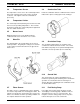
2 THERMO 90 / 90 S GENERAL DESCRIPTION 1 2 3 4 5 6 7 8 9 10 11 Heater Thermo 90 S 2.1 Combustion Air Fan The combustion air fan delivers the air required for combustion from the combustion air inlet to the burner insert. 2-2 2.
THERMO 90 / 90 S 2.3 Temperature Sensor The temperature sensor senses the coolant temperature in the heat exchanger of the heater unit as electrical resistance. This signal is fed to the control unit for processing. 2.4 2 2.8 GENERAL DESCRIPTION Combustion Tube Inside the combustion tube the combustion of the fuel/air mixture takes place, heating up the heat exchanger. Temperature Limiter The overheat protection (bimetal) protects the heater unit from excessive operating temperatures.
THERMO 90 / 90 S 3. 3.1 Functional Description (Fig. 3-1) Switch-on When operating the push button "Immediate Heating", the "Operating Indicator" on the timer illuminates 3 3.4 FUNCTIONAL DESCRIPTION Switch-off When switching the heater off, the operation indicator on the timer/switch extinguishes. Combustion ends and the run-down cycle is initiated.
3 Fig. 3-1 Functional Sequence for Thermo 90/90 S 1 2 3 4 5 6 7 8 9 10 11 12 13 14 15 16 17 18 19 20 21 22 23 Switch-on Configuration Check Preheating 40 sec. (cycled) Fuel Dosing Pump Priming 5 - 7 sec. (1) Fuel Dosing Pump / Part Load (1/4) Flame Sensor Take-over Stabilization Period Full Load Vehicle Blower ‘On’ (optional) Control Range Control Idle Flame Sensor ‘cold’ (0) Run-down completed Preheating 15 - 20 sec. (cycled) Fuel Dosing Pump Priming 5 - 7 sec.
THERMO 90 / 90 S 3 FUNCTIONAL DESCRIPTION 3.5 Malfunctions 3.5.3 3.5.1 Switch-off upon Failure When equipped with a standard timer model 1531, an error code will be indicated on the timer display: In case of a no-flame condition, fuel is delivered for a maximum of 180 seconds. In the event of a flame-out during operation, fuel is delivered for a maximum of 90 seconds. Should an overheat condition exist (after response of the temperature limiter), no fuel will be delivered.
THERMO 90 / 90 S 4. 4 Technical Data (Standard Measure) As long as no threshold values are given, the following technical data is understood to include tolerances of ±10% usual for heaters at an ambient temperature of +68 °F and at nominal voltage and conditions. Coolant Heater TECHNICAL DATA Electrical Components: Control unit, combustion air fan motor and fuel dosing pump, glow pin, control switch and timer are either of the 12V or 24V type.
4 THERMO 90 / 90 S TECHNICAL DATA 4. Technical Data (Metric Measure) As long as no threshold values are given, the following technical data is understood to include tolerances of ±10% usual for heaters at an ambient temperature of +20 °C and at nominal voltage and conditions. Coolant Heater Electrical Components: Control unit, combustion air fan motor and fuel dosing pump, glow pin, control switch and timer are either of the 12V or 24V type.
THERMO 90 / 90 S 5 5. Troubleshooting 5.1 General This section describes troubleshooting procedures for the Thermo 90 and Thermo 90 S coolant heaters. TROUBLESHOOTING CAUTION Troubleshooting is normally limited to the isolation of defective components. The following defects are not included in the troubleshooting procedures.
5 THERMO 90 / 90 S TROUBLESHOOTING 5.3 Failure Symptoms after Switch-off upon Failure NOTE: When operated with a switch the type of failure is indicated by a flash code of the operation indicator light during heater run-down. The heater Thermo 90 S, with standard timer, outputs errors to the timer display for indication (see 3.6.3). The following table may also be used as representative reference. After five short signals the long flash pulses are counted.
THERMO 90 / 90 S 5 TROUBLESHOOTING Failure Symptom Probable Cause Remedy 8 Flash pulses (F 08) (combustion air fan) Wiring Check wiring for damage, open connections or short circuit Replace replace combustion air fan Combustion air fan defective 9 Flash pulses (F 09) (glow pin) Wiring Check wiring for damage, open connections or short circuit Replace glow pin Glow pin defective 10 Flash pulses (F 10) (temperature limiter Thermo 90 S only) Coolant circuit Check coolant level Bleed coolant circu
5 5.5 THERMO 90 / 90 S TROUBLESHOOTING Visual Inspection for Assessment of Burner Condition 5.5.1 • Burner and evaporator have specific features indicating their need for replacement or their serviceable condition. The following describes the criteria for a correct inspection. Burner Housing The starting air bore (Fig. 5-3) must not be clogged, otherwise there will be no start. Remedy Carefully remove any contamination with a wire of 1.5 mm diameter. Remove glow pin first. 1 2 3 4 5 6 7 8 9 Fig.
THERMO 90 / 90 S 5.5.2 • Rear Wall with Metal Evaporator The pilot flame exit bore (Fig. 5-4) must not be clogged, otherwise there will be no start. 5 5.5.3 • Remedy Replace burner assembly • • Cracks, delaminations, as well as black or other discolorations of the evaporator do not cause a burner failure and are meaningless. Coke deposits on the evaporator surface (except for the pilot flame exit bore) are normal and must not be removed.
THERMO 90 / 90 S 6 FUNCTIONAL TESTS 6. Functional Tests 6.3.3 6.1 General During electrical testing of the flame sensor using a digital multi-meter, the following readings should be obtained: This section describes the on-vehicle and off-vehicle testing of the heater to check for proper operation. WARNING The heater must not be operated, not even with timer, in enclosed areas like garages or workshops not equipped with an exhaust venting facility.
THERMO 90 / 90 S 7 CIRCUIT DIAGRAMS 7. Circuit Diagrams The circuit diagrams (Figs. 7-3 and 7-5) show possible circuits of the Thermo 90 S heater with: 7.1 General • The circuit diagrams (Fig. 7-2 and 7-4) show possible circuits of the Thermo 90 heater with: • • with standard switch and harness wiring using Deutsch connector and blower interlock wiring with Deutsch connector – North American enclosure & compact kits (see Fig. 7-2).
7 CIRCUIT DIAGRAMS Fig.
THERMO 90 / 90 S Fig.
7 CIRCUIT DIAGRAMS THERMO 90 / 90 S Thermo 90 Basic Kit Wiring (German) Fig.
THERMO 90 / 90 S 7 CIRCUIT DIAGRAMS Thermo 90 S Basic Kit Wiring (German) Fig.
THERMO 90 / 90 S 8 SERVICING 8. Servicing 8.5 8.1 General Before or after each heating season the following maintenance procedures should be performed to maintain the heater's functional reliability: This section describes the servicing procedures that may be performed with the heater installed. 8.2 Work on the Heater Prior to performing any work, it is mandatory to disconnect the vehicle battery main lead.
8 THERMO 90 / 90 S SERVICING NOTE: The manufacturer mounts the control unit of Thermo 90 S heater to the combustion air fan.
THERMO 90 / 90 S 8.6 8.6.1 8 Visual Inspections and Installation Regulations Connection to the Vehicle's Cooling System In thermostat circuits only thermostats opening at < 65 °C (149 °F) are to be used. 8.6.2 SERVICING Connection to the Vehicle's Fuel System Fuel is tapped from the fuel reservoir of the vehicle or from a separate fuel container. Fuel lines must be of the type as described in section 8.6.2.2 of this manual. The fuel system limitations are illustrated in Fig. 8-2.
8 THERMO 90 / 90 S SERVICING 8.6.2.1 Fuel Tapping Fuel tapping must be from the fuel reservoir or from a separate tank (Fig. 8-3). This separate fuel tapping avoids an influence on the pressure. Vehicles with Gasoline Engines In combination with carburetor equipped or fuel injected gasoline engines with a return line, the heater's fuel system integration must be in the return line.
THERMO 90 / 90 S 8.6.2.2 8 8.6.3 Fuel lines Fuel lines may only be steel, copper, or plastic lines made of unhardened, light and temperature stabilized PA 11 or Pa 12 (e.g. Mecanyl RWTL) according to DIN 73378. SERVICING Fuel Dosing Pump The fuel dosing pump is a combined delivery, dosing, and shut-off system and is subject to certain installation criteria (see Figs. 8-2 and 8-5).
8 THERMO 90 / 90 S SERVICING 8.6.3.2 Installation and Attachment 8.6.6 Exhaust Line The fuel dosing pump is to be attached with anti-vibration mounts. The installation location is limited according to Fig. 8-5 to ensure sufficient self-bleeding capability. Due to the danger of corrosion, the plug connection between fuel dosing pump and fuel dosing pump cable loom may only be fitted with Webasto original spare parts. The exhaust line (inner diameter 38 mm or 1.5 in.) may have a length from 0.
THERMO 90 / 90 S 8.7 Removal and Installation CAUTION It is permissible to service the heater in the installed position only if sufficient space is available for removal and disassembly of the various components of the heater. Should there not be sufficient space or there exists a possibility of damage to the components of the heater during disassembly, the heater must be removed from the installed position. 8.7.1 Heater, Removal and Installation 8.7.1.1 Removal 8 8.7.
THERMO 90 / 90 S 9. Repair 9.1 General This section describes the repairs that may be performed on the heater Thermo 90 Thermo 90 S when removed. Any further disassembly will void the warranty. For re-assembly only Webasto-authorized spare parts kits are to be used. 9.1.1 Work on Components after Disassembly 9 9.1.1.1 • • • Cleaning All disassembled components must be cleaned. 9.1.1.2 • REPAIR Visual Inspection Examine all components for damages (cracks, deformation, wear, etc.
9 THERMO 90 / 90 S REPAIR 9.2 Disassembly and Assembly 9.2.1 Electrical Connections (Fig. 9-1) 9.2.1.1 Disconnecting Electrical Connections (Connection X1) NOTE: All electrical connections are joined in the connector. Prior to removal of a component, the relevant electrical connections first have to be disconnected.
THERMO 90 / 90 S 9 REPAIR 9.2.2 Replacement of Circulation Pump 9.2.2.2 9.2.2.1 Removal 1. Apply acid free grease (Vaseline) to gasket (1, Fig. 9-2) 2. Bring circulation pump (2) in assembly position and secure using clamp (3) and screws (4). 3. Torque screws (4) to 3 Nm + 10%. 4. Make electrical connections (see 9.2.1.2). 5. Install heater (see 8.7.1.2). 1. 2. 3. 4. 5. Remove heater (see 8.7.1.1). Disconnect electrical connections (see 9.2.1.1). Remove screws (4, Fig. 9-2).
9 THERMO 90 / 90 S REPAIR 9.2.3 Replacement of Temperature Limiter 9.2.4 Replacement of Temperature Sensor 9.2.3.1 Removal 9.2.4.1 Removal NOTE: Perform the following procedure only when the temperature limiter needs replacement. A functional check has to be performed when the temperature limiter is installed. 1. Remove heater (see 8.7.1.1). 2. Disconnect electrical connections (see 9.2.1.1). 1. Remove heater (see 8.7.1.1). 2. Disconnect electrical connections (see 9.2.1.1). 3.
THERMO 90 / 90 S 9 REPAIR NOTE: One of the newer models Thermo 90 shown. Older models have the cable of the temperature limiter located on the side. Heater Thermo 90 S may have the control unit located on the combustion air fan not affecting the replacement of the temperature limiter and temperature sensor. Fig.
9 THERMO 90 / 90 S REPAIR 9.2.5 Replacement of Combustion Air Fan 9.2.5.2 9.2.5.1 Removal NOTE: Locate packing ring (3, Fig. 9-4) properly; do not squeeze. 1. 2. 3. 4. Remove heater (see 8.7.1.1). Disconnect electrical connections (see 9.2.1.1). Remove screws (2, Fig. 9-4). Pull combustion air fan (1) from burner head (4) and remove together with profiled packing ring (3). NOTE: On heater Thermo 90 S with flanged control unit remove control unit as required. 5.
THERMO 90 / 90 S 9.2.6 Replacement of Burner, Flame Sensor and Glow Pin 9.2.6.1 Removal 1. 2. 3. 4. 5. 6. 7. 8. 9. 9 REPAIR CAUTION When performing the following step, ensure that cables of flame sensor (7) and glow pin (6) are routed as shown in figure. Remove heater (see 8.7.1.1). Remove combustion air fan (see 9.2.5.1). Remove screw (5, Fig. 9-5) and washer (4). Remove nuts (10) and withdraw bracket. Withdraw grommets (11 and 12) from slots in housing of combustion tube (3).
9 THERMO 90 / 90 S REPAIR NOTE: One of the newer models of Thermo 90 shown. Older models have the cable of the temperature limiter located on the side. Illustration is also applicable to the Thermo 90 S. Fig.
THERMO 90 / 90 S 9 REPAIR 9.2.7 Replacement of Burner Head 9.2.7.2 9.2.7.1 Removal NOTE: Burner head and exhaust outlet pipe can still be aligned during installation in vehicle. 1. Remove heater (see 8.7.1.1). 2. Remove combustion air fan (see 9.2.5.1). 3. Remove burner, flame sensor and glow pin (see 9.2.5.1). 4. Remove attachment screw of V-clamp (2, Fig. 9-6) and pull off clamp. 5. Withdraw burner head (1) from heat exchanger (3) and remove. 6.
9 THERMO 90 / 90 S REPAIR 9.2.8 Replacement of Heat Exchanger 9.2.8.2 9.2.8.1 Removal 1. Clip connector housing onto heat exchanger and engage connector in connector housing. 2. Install burner head (see 9.2.7.2). 3. Install burner, flame sensor, and glow pin (see 9.2.6.2). 4. Install combustion air fan (see 9.2.5.2). 5. Install temperature sensor (see 9.2.4.2). 6. Install temperature limiter (see 9.2.3.2). 7. Install circulation pump (see 9.2.2.2). 8. Install heater (see 8.7.1.2). 1. 2. 3. 4. 5.
Coolant Heater Thermo 90 Thermo 90 S Workshop Manual Webasto Thermosystems Inc. North America 3333 John Conley Drive Lapeer, MI 48446 Phone (810) 245-2400 Toll-free (800) HEATER-1 Fax (810) 664-7720 Technical Assistance Hotline USA: (800) 555-4518 Canada: (800) 667-8900 Rev. 03/2000 907400 www.webasto.