Water Heater Unit Feel the drive e1 Thermo Top E Auxiliary Heating 00 0003 e1 Thermo Top C Auxiliary Heating 00 0002 Installation Instructions Mazda 3 MPS Gasoline From model year 2006 For left-hand drive vehicles only WARNING! Hazard warning: Incorrect installation or repair of Webasto heating systems may cause a fire or result in the emission of carbon monoxide, which can be fatal. Serious or fatal injuries can be caused as a result.
Mazda 3 MPS Table of Contents Validity Heater Unit / Installation Kit Foreword General Instructions Special Tools Explanatory Notes on the Document Preliminary Work Heater Unit Installation Location Preparing the Electronics Electrical Connections Automatic air conditioning blower control Remote Start Option 2 3 3 3 3 4 5 5 6 8 9 12 Preparing the Installation Location Installing the Heater Unit Exhaust System Fuel Connection Combustion Air Water Connection for Gasoline Engines Final Work Operating instruc
Mazda 3 MPS Heater Unit / Installation Kit Amount 1 1 Description Commercial supply of required control Installation kit for Mazda 3 MPS Gasoline Order no.: See price list 1,311,467A Recommended heater unit for the relevant vehicle class: Vehicle Compact car Mid-class, station wagon Luxury, van, off-roader Heater unit Thermo Top E Thermo Top C Thermo Top P The choice of heater unit is based on the size of the vehicle passenger compartment and the customer's comfort requirements.
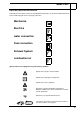
Mazda 3 MPS Explanatory Notes on the Document To provide you with a quick overview of the individual working steps, you will find an identification mark on the outside top right corner of the page in question. Mechanics Electrics water connection Fuel connection Exhaust System combustion air Special features are highlighted using the following symbols: Specific risk of injury or fatal accidents. Specific risk of damage to components. Specific risk of fire or explosion.
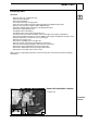
Mazda 3 MPS Preliminary Work WARNING! - Open the tank cap, ventilate the tank. Close the tank cap again. Disconnect the battery. Let off pressure in the cooling system. Copy the factory number from the original type label to the duplicate type label. Remove years that do not apply from the duplicate label. Attach the duplicate label (type label) in the appropriate place. Remove the engine design cover. Completely remove the battery. Completely remove the air filter with intake hose.
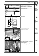
Mazda 3 MPS Preparing the Electronics 1 2 sw 2,5mm² Only for automatic air conditioning 250mm 2250mm 3 4 1500mm Wire section 4 will be needed later for connecting the resistor. br 2,5mm² 1000mm 5 Cutting wires into sections sw 0,5mm² 1500mm 6 sw 0,5mm² 250mm Wire sections br 6 sw 2 85 30 Preassemble the K3.1 relay K3.
Mazda 3 MPS Put the remaining flexible hose 1 on the positive cable on the heater unit cable harness 2. Connect the positive cable to the positive battery terminal 3.
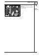
Mazda 3 MPS Electrical Connections Cable harness feed-through Time switch and summer / winter switch option 1 Protective rubber sleeve 1 Time switch 2 Summer / winter switch 1 1 2 5 6 rt sw br bl Cable harness installation diagram br sw sw 1 Wait to install the metering pump cable harness until later, together with fuel pipe along the original vehicle fuel lines on the underbody. 2 1 3 2 4 7 8 Fuse holder, K3 relay, K3.1 relay 0.
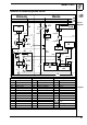
Mazda 3 MPS Automatic air conditioning blower control Webasto HG X1 Mazda K1 F3 F44 Circuit diagram PJB J-03 4 rt/ws 86 sw/bl rt gn/ws 30 ge 0,5mm² C-04 sw ro/or 4mm² 87a 87 85 ge 0,5mm² K3 B sw br R1 br 4 30 75 15 sw/rt sw 2 85 sw/or ro/or 4mm² sw br 6 R sw/gn bl/sw 30 K3.1 86 87 sw br sw/gn sw M 87a sw G1 G2 1 3 5 31 Webasto components HG Heater unit TT-C/E X1 6-pin connector F3 Fuse, 25A K3 Blower relay K3.1 Supplementary relay R1 0.
Mazda 3 MPS Connection to the connector 3 C-04 Connect with enclosed connectors according to the circuit diagram. 2 1 3 1 2 4 5 Wire (sw) from K3/30 Pink/orange (ro/or) wire to blower motor. Pink/orange (ro/or) wire to connector C-04. Red (rt) wire from F3/87a 5 Positive connection to the blower motor 9 4 1 Connector C-04 2 Pink/orange (ro/or) slot. 2 1 Connector C-04 10 1 2 Connection to 6-pin connector 4 from the blower control. 3 1 2 3 5 5 Brown (br) wire from K3.
Mazda 3 MPS 1 2 3 Pull the connection to connector 5 J-03 from the PJB fuse and relay support. Connect with enclosed butt connector 3 according to the circuit diagram. 1 Yellow (ge) wire 2 Black (sw) wire from K3.1/86 4 Yellow (ge) wire Relay K3.
Mazda 3 MPS 1 2 Remote Start Option 3 1 Receiver 2 Bracket, drill hole in bracket to Ø6.5mm.
Mazda 3 MPS Preparing the Installation Location 1 Remove the blower resistor 1 17 Drill Ø 7mm holes1 [2x] in the bracket 2 according to the illustration. 1 1 107mm 114mm 30mm Preparing the bracket 18mm 2 18 Drill open holes 1[2x] in the strut 2 to Ø10mm. 1 1 19 2 1 5 Preparing the strut 2 Assemble the bracket 2 according to the image, transfer hole images 3 and 4. 3 4 1 M6x20 bolt, 5 mm spacer washer, original vehicle threaded insert 3 Hole image for Ø 9.
Mazda 3 MPS Remove original vehicle bolt 2, this will be used again. 1 1 M6 rivet nut 3 Hole Ø 7mm 2 Tighten the rivet nut; remove the screw 3 21 1 Blower resistance 2 M6x20 bolt, spring washer, body washer, 8mm spacer washer, original vehicle threaded insert 1 Assemble blower resistor 22 2 1 Preassemble the bracket 3 with the bracket 2 according to the illustration.
Mazda 3 MPS 1 Installing the Heater Unit 2 6 3 5 4 Assemble the pre-assembled bracket according to the illustration. Resistor retaining plate 1 is assembled together with the bracket 3, spring washer 6, body washer 6, spacer 5mm 6, original vehicle threaded insert 6. Assembling the bracket 2 M6x20 bolt, spring washer, rivet nut 4 M6x70 bolt, 20 mm spacer, 30 mm spacer, M6 flanged nut 5 M6x70 bolt, 15mm spacer nut, 30 mm spacer, M6 flanged nut 25 1 Figure 18 is the rear view of figure 17.
Mazda 3 MPS Prepare the strut according to the illustration 3 1 1 Original vehicle bolt [see page 14, figure 21] 2 Strut 3 5mm spacer disc Assembling the strut 29 2 1 Original vehicle bolt 2 Strut 3 Spacer nut M6x30 1 2 Assembling the strut 3 30 1311472A 16
Mazda 3 MPS 1 Exhaust System 2 1 Exhaust pipe a = 440mm 2 Exhaust end section b = 50mm Dispose of section X a Preparing the exhaust pipe b X 1 Ensure sufficient distance from adjacent components.
Mazda 3 MPS Fuel Connection CAUTION! Open the vehicle's tank-cap lock, ventilate the tank and then re-close the tank lock. Catch any fuel running off with an appropriate container. Install fuel line and metering pump cable harness so that they are protected against stone impact. Unless specified otherwise, always fasten using cable clips. Fit the fuel line and cable harness with edge protectors around sharp edges.
Mazda 3 MPS 1 Placement of the fuel pipe 2 is done together with the metering pump cable harness 1 to the vehicle underbody along the original vehicle lines, secure with cable ties. 2 Placing the fuel pipe 35 Installation location of the metering pump 1 is to the right next to the vehicle tank. Run the fuel pipe from the heater unit 2 and metering pump cable harness 3 to the metering pump installation location 1.
Mazda 3 MPS Shape, cut into sections, and insert the tank extracting device according to the template, see the Installation Instructions. Re-assemble tank mounting! 1 2 1 Tank extracting device 2 Tank mounting Inserting tank extracting device 39 Install the tank mounting according to manufacturer's instructions.
Mazda 3 MPS Combustion Air Run the combustion air line 1 according to the figure. Placement of the combustion air line 43 1 Note the spatial requirements for the engine filter housing. Fasten the intake silencer 3 to the cable harness 2with cable ties1.
Mazda 3 MPS Water Connection for Gasoline Engines WARNING! Tighten all hose clamps to 2.0 + 0.5 Nm. Any coolant running off should be collected using an appropriate container! Route hoses so that they are kink-free. Unless specified otherwise, always fasten using cable clips. Position hose clamps and spring band clamps so that no other hose can be damaged. The connection should be "inline" based on the following diagram: Water installation diagram A Ø 17x20 Ø 18x18 C 1 B All hose clamps = Ø 20-27 mm.
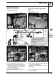
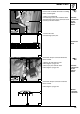
Mazda 3 MPS b = 450mm c = 660mm C B Dispose of section X Cut the braided protective hose into sections and slide it onto hose B and hose C. X b X c Cutting water hoses into sections A Cut the braided protective hose in the middle and slide it onto hose B and hose C. Cut shrink-fit hose to size. B 1 1 1 25 mm shrink-fit hose [4x] 2 Black (sw) rubber profile 2 150 1 Preparing the water hoses 1 C Turn the original vehicle clamp 1 down.
Mazda 3 MPS 1 Original vehicle engine exhaust hose 2 Cut location 2 1 Splitting point 47 1 1 Engine exhaust hose section A Connection of moulded hose A: 48 1 Heater unit B Connecting hose B on the heater unit 1 49 Align the rubber profile 1.
Mazda 3 MPS C 1 Heater unit 2 Cable clips 1 2 Connecting hose C on the heater unit 51 Before connecting, fill the water hoses with coolant. Insert the hose bracket 1 as shown in the figure. 1 B 2 Heat exchanger inlet hose section 2 52 C 1 Connecting to the heat exchanger inlet C Prepare the water hoses with cable clips 1 according to the figure.
Mazda 3 MPS Final Work WARNING! Reassemble disassembled components in reverse order. Check that all hose lines, clips, and all electrical connections are securely fastened. Secure all loose cables using cable clips. Only use manufacturer-approved coolant. Spray heating unit components with anti-corrosion wax (Tectyl 100K, Order No. 111329). - Connect battery. Fill and bleed the coolant circuit according to the vehicle manufacturer’s specifications. Set the time switch.
Mazda 3 MPS Operating instructions for the end customer Please remove page and add to the vehicle operating instructions. Before parking the vehicle, make the following settings: 1 Blower rpm is pre-set in auxiliary heating operation 2 Air outlet to windscreen 3 Temperature to "max." For vehicles with automatic air conditioning 1 2 3 56 For short distance trips, it is not recommended that the rear window heating be used. Rule of thumb for operating the auxiliary heating: driving time = heating time.
Mazda 3 MPS Tank Extracting Device Template 100mm Scale 1:1 Compare the size of the printed version with dimension lines. Permitted tolerance a maximum of 2%.