Water Heater Unit Feel the drive Thermo Top C Auxiliary Heating e1 00 0002 Installation Instructions Mercedes-Benz E-Class BR 211 / CLS BR 219 Gasoline and diesel from the 2003 model For left-hand drive vehicles only Not for AMG or AMG look WARNING! Hazard warning: Incorrect installation or repair of Webasto heating systems may cause a fire or result in the emission of carbon monoxide, which can be fatal. Serious or fatal injuries can be caused as a result.
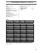
Mercedes-Benz E-Class BR 211 / CLS BR 219 Table of Contents Validity 2 Heater Unit / Installation Kit 3 Foreword 3 General Instructions 3 Special Tools 3 Explanatory Notes on the Document 4 Preliminary Work 5 Tips and Tricks / Preparing the Electrical 6 Preparing the Heater Unit / Installing the Heater Unit 7 Electric diagram 8 Installing the Wiring harness / Electrical Connection 9 T90 remote receiver /SPAL remote receiver 10 Routing the Fuel Pump Wiring Harness 11 Water diagram 12 Turning the Water Pump 1
Mercedes-Benz E-Class BR 211 / CLS BR 219 Heater Unit / Installation Kit Amount 1 1 Description Scope of delivery TT-C Diesel W211 / W219 Scope of delivery TT-C Gasoline W211 / W219 Order No.
Mercedes-Benz E-Class BR 211 / CLS BR 219 Explanatory Notes on the Document To provide you with a quick overview of the individual working steps, you will find an identification mark on the outside top right corner of the page in question. Mechanics Electrics Water connection Fuel connection Exhaust system Combustion air Special features are highlighted using the following symbols: Specific risk of injury or fatal accidents. Specific risk of damage to components. Specific risk of fire or explosion.
Mercedes-Benz E-Class BR 211 / CLS BR 219 Preliminary Work - Slide the passenger seat backwards as far as possible. Remove the vehicle keys from the ignition. Disconnect the battery. (in the trunk) Remove the side cover of the fuse box on the driver’s side of the dash board. Remove the footwell panel under the dashboard on the passenger side. Remove the A-pillar panel in the passenger side. Remove the floor cover in the passenger footwell area. Loosen the footrest plate located behind this.
Mercedes-Benz E-Class BR 211 / CLS BR 219 1 2 Loosen the bumper on the side facing the wheel well: Loosen the screws, move the clamping bar to the front and remove it. 1 Clamping bar 2 Bolt 3 Coolant hose to the heater unit (will be added Later, not yet present during disassembly) Tips and Tricks 3 2 To route wiring harnesses and wires through grommets, cable ducts or tight areas, we recommend using the mecanyl fuel line.
Mercedes-Benz E-Class BR 211 / CLS BR 219 Preparing the Heater Unit 1 2 Place the solenoid valve and bracket on the stay bolts in the heater unit and fasten with the flanged nuts. Fasten the preassembled coolant hose with the spring band clamp to the solenoid valve. Replace the connector on the solenoid valve.
Mercedes-Benz E-Class BR 211 / CLS BR 219 Electrical Connections CAN junction Ground connection 1 Heater wiring harness 2 CAN plug connector 1 Grounding point in passenger foot area 2 1 1 8 9 Wiring harness installation diagram 2 1 3 2 1 6 5 10 Dashboard fuse box 1 Fasten the heater unit fuse holder on the free slot in the left row, fifth from the top (position 25) 2 Dashboard fuse box left 4 11 T90 and SPAL remote control elements (schematically pre-assembled) 1 Heater harness 2 Remote ant
Mercedes-Benz E-Class BR 211 / CLS BR 219 Installing the wiring harness 1 Unclip the harness conduit cover on the right suspension strut mount, remove the harness grommet from the guide. Cut the side of the grommet and insert the Webasto wiring harness. Seal the grommet with adhesive sealant and reinstall in guide. Wiring harness routing 1 Webasto wiring harness 2 Cut open grommet C 12 2 The figure shows coolant hose C covered with braided hose protection.
Mercedes-Benz E-Class BR 211 / CLS BR 219 T90 Remote Receiver 1 Attach Velcro strips to the receiver. 1 Receiver 2 Velcro strips T90 Remote preparation 2 16 1 2 3 SPAL Remote Receiver 1 Receiver antenna 2 SPAL remote receiver 3 Remote harness from Y-adapter harness SPAL Remote preparation 17 1 2 Note: Note the chapter “Final work“on page 22“ Fasten the T90 remote receiver on the rear side of the glove compartment.
Mercedes-Benz E-Class BR 211 / CLS BR 219 Route the wiring harness for the fuel pump 1 Route the connector for the wiring harness for the fuel pump through the cable conduit to the rear seat bench. Route behind the back cover next to the arm rest to the plug connector. Place in cable conduit 1 Cable conduit cover 2 Rocker panel cable conduit 2 20 Remove the red gasket piece from the free slot in the terminal strip (no longer needed). Insert the connector for the fuel pump wiring harness in the slot.
Mercedes-Benz E-Class BR 211 / CLS BR 219 Water Connection Attention: Any coolant running off should be collected using an appropriate container! Install hoses so that they are kink-free. Unless specified otherwise, always fasten using cable ties.
Mercedes-Benz E-Class BR 211 / CLS BR 219 1 Route the fuel line under the air intake silencer to the wheel house cross member. Fasten to cross member with it two fastening clips and route to the wheel house. 1 Fastening clips [2x] 2 Fuel line Fuel line installation 2 24 Water Connection Disconnect both coolant hoses to the original vehicle electric water pump with pliers and remove. Pull the plug off.
Mercedes-Benz E-Class BR 211 / CLS BR 219 Connect the disassembled coolant hose back on the electric water pump as shown in Figure 28. 1 Water pump 2 Coolant hose 1 2 Assembling the coolant hoses 28 Put the braided hose protection on the end of the moulded hose. Pre-assemble two clamps. 1 Braided hose protection 1=100 mm 2 Spring band clamps Ø25 mm [2x] A Moulded hose 1 A Coolant hose preassembly 2 29 Before connecting, fill the coolant hoses with coolant.
Mercedes-Benz E-Class BR 211 / CLS BR 219 Replacing the Switch Valve 1 Loosen the hose on the top of the switch valve on the rear bulkhead and loosen the plug. Loosen the hose connections by pulling out the spring wires [3x]. Remove the rubber sleeve. Remove the valve. 2 Removing switch valve 1 Protective rubber sleeve 2 Engine outlet hose 32 1 B 2 33 Before connecting, fill the coolant hoses with coolant! Install new switch valve (5 connections). Replace protective rubber sleeves.
Mercedes-Benz E-Class BR 211 / CLS BR 219 Place the moulded coolant hose in the gap in the windshield fluid container and then along the wiring harnesses under the container shackle. B 1 Windshield fluid container shackle B Moulded coolant hose 1 Routing the coolant hose 36 1 2 3 4 Slide the long remnant of the braided hose protection on hose C l=800 mm. On one side, slide on the red rubber insulator. On both sides, insert the coolant hose couplers and fasten with clamps.
Mercedes-Benz E-Class BR 211 / CLS BR 219 Route the coolant hose on the side over the bracket and down into the fender. (Figure shows CLS, always check for access to the headlight!) Routing the coolant hose 40 Connect the coolant hose to the preassembled hose on the solenoid valve.
Mercedes-Benz E-Class BR 211 / CLS BR 219 Fuel Connection Remove the vehicle's fuel tank cap, ventilate the fuel tank and reinstall fuel tank cap. CAUTION! Catch any fuel running off with an appropriate container. Install the fuel line so that they are protected from impact by rocks! Unless specified otherwise, always fasten using cable ties. Fit the fuel line and wiring harness with edge protectors around sharp edges.
Mercedes-Benz E-Class BR 211 / CLS BR 219 1 2 3 Assembling the fuel pump 4 1 2 3 4 Fuel line coupler 90° Fuel pump Rubber bracket Universal clamp Ø10 mm, (white color identification) [4x] 5 Fuel line coupler [2x] 6 Mecanyl fuel line 1=130 mm 6 Fuel pump preassembly 5 45 Install the fuel pump mounting bracket (with M6x25 collar screw) on the original vehicle bolts with plastic nuts.
Mercedes-Benz E-Class BR 211 / CLS BR 219 Insert a screw driver in the fuel pump mounting bracket hole and bend the strap to align it for free access to the fuel pump from the adjacent components. 2 1 Suction side of the fuel line 2 Fuel pump mounting bracket 1 Align the fuel pump bracket 49 Cut the fuel line on the fuel pump into sections and connect to the fuel pump outlet (side with connector) with fuel line coupler and clamps. Route the connector for the fuel pump to the fuel pump and connect.
Mercedes-Benz E-Class BR 211 / CLS BR 219 Final Work WARNING! Reassemble disassembled components in reverse order. Check that all hose lines, hose, spring band clamps and universal clamps, and all electrical connections are securely fastened. Secure all loose lines using cable ties. Check and adjust any disassembled or loose headlights after installation. Spray heating unit components with anti-corrosion wax (Tectyl 100K, Order No. 111329).
Mercedes-Benz E-Class BR 211 / CLS BR 219 NOTES: 22
Mercedes-Benz E-Class BR 211 / CLS BR 219 Documentation Feedback Form Detailed user feedback is extremely valuable to us in producing accurate, comprehensive, and useful documentation Please complete the relevant parts of the form below; your comments and suggestions will help us improve our documentation. Thank you. Unsatisfactory Excellent Please rate the overall usefulness of the documentation.
F e e l t h e d r iv e Webasto Product N.A., Inc. Technical Assistance Hotline USA: (800) 555-4518 Canada: (800) 667-8900 Org.07/2006 Rev. N/A P/N 5001169A www.webasto.us www.techwebasto.