Coolant Heaters Thermo 230.036 Thermo 300.
Thermo 230/300 Contents Contents 1. Introduction 1.1 General Description......................................................................................................... 1.2 Legal Provisions .............................................................................................................. 1.3 Meaning of Warning, Caution and Note .......................................................................... 101 102 102 2. Operating your Webasto Heater 2.1 Switching On.....................
Thermo 230/300 Contents 5. Maintenance of the Heater 5.1 Annual Maintenance........................................................................................................ 501 6. Basic Troubleshooting 6.1 General Information ......................................................................................................... 6.2 Operational Failure Symptoms (Reading the flash code) ............................................... 6.2.
Thermo 230/300 Contents List of Tables 201 301 302 601 Digital Timer Instructions ................................................................................................. Thermo 230/300 Heater Data.......................................................................................... Coolant Circulation Pump Data ....................................................................................... Operational Failure Symptoms via Fault/Flash Code.............................................
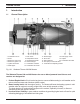
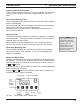
Thermo 230/300 1 1. Introduction 1.1 General Description 1 2 3 4 5 6 Combustion air fan Motor Electronic control unit Electronic ignition coil Ignition electrodes Water pipes 7 8 9 10 11 12 Fuel nozzle Temperature sensor Overheat thermostat Heat exchanger Combustion chamber Combustion air swirler 13 14 15 16 17 Introduction Exhaust pipe 18 Fuel supply / return Photo disc 19 Coupler Flame detector 20 Combustion air intake Fuel pump w/ solenoid valve Combustion air adjusting shutter Fig.
1 Thermo 230/300 Introduction 1.2 Legal provisions Heater installation must be performed in accordance with the manufacturer`s installation instructions. Any deviations from these instructions are only permitted with written approval from Webasto Thermosystems. Installations not complying with the installation instructions will release Webasto Thermosystems from any product liability. OEM installations must be approved by Webasto Thermosystems. 1.
Thermo 230/300 2. 2 Operating your Webasto Heater Operating your Webasto Heater Before switching the Webasto water heater on, set vehicle heating system to the “heat” position and open any shut off valves. Depending on the type of control installed in the of the vehicle, the heater can be operated by the following methods. 2.
2 2.2 Operating your Webasto Heater Switching Off When heating is no longer required, switch the Webasto heater off. The solenoid valve interrupts the fuel supply, combustion stops and the indicator light turns off. The Combustion air fan and the water pump remain on for another 2-3 minutes (after run cycle) purging the combustion chamber of any fumes. 2.3 Engine Pre-heating 1. Set the timer 30 min. to 1 hr. before you want to start engine. The heater will start up at set time.
Thermo 230/300 2 Operating your Webasto Heater Programmed Heater Operation Three memory locations numbered 1 to 3 are available. Each memory location can be assigned a given time together with the day of the week. Pre-selected Starting Times The pre-selected starting time is the time at which the heater switches itself on automatically. We recommend that memory locations 1 and 2 be used for presetting starting times within 24 hours of setting the timer.
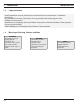
2 2.6 Operating your Webasto Heater 7-Day Digital Timer Programming and Operating Instructions Setting the time and day of the week Press the button for more than 2 seconds. Time display flashes. Press the or button to set time of day. Wait 5 seconds. Time is now stored. Day of week flashes. Press or button to set day of week. Wait 5 seconds. Day of week is now stored. Viewing the time With ignition “ON”: Continuous display of current time and day of the week. With ignition “OFF”: Briefly press button.
Thermo 230/300 3 3. Technical Data 3.1 Thermo 230/300 Heater Data Thermo 230 Heater Thermo 300 Coolant Heater with High Pressure Fuel Nozzle Design Heat Output BTU/hr (kW) 80,000 (23) 104,000 (30) Diesel #1, Diesel #2, Arctic and Kerosene Fuel Fuel Consumption max. Technical Data Kg/hr (US. gal/hr) 2.5 (0.8) 3.3 (1.2) Rated Voltage (V) 24 Operating Voltage (V) 20 ...
3 3.1.1 Technical Data Thermo 230/300 Heater Dimensions Fig.
Thermo 230/300 3.2 3 Technical Data Coolant Circulation Pump Data U 4814 U 4851 5200 (22.9) against 0.2 mbar 6000 (26.4) against 0.4 mbar Circulating Pump Flow Rate l/hr l/h (gal/min) Rated Voltage (V) 24 24 Operating Voltage Range (V) 20 ... 28 18 ... 32 Power Consumption (W) 104 209 221 mm (8.7 in.) 100 mm (3.94 in.) 105 mm (4.14 in.) 285 mm (11.22 in.) 115 mm (4.52 in.) 110 mm (4.33 in.) mm (inch) O.D. 38.0 (1.5) 38.0 (1.5) kg (lb) 2.1 (4.63) 2.7 (5.
3 Technical Data Fig. 303 Coolant Circulating Pump Assembly - U 4851 Fig.
Thermo 230/300 4. Installation 4.1 General Information Webasto will take you step by step through the installation process to ensure successful operation for years to come. The installation must be performed in accordance with the installation instructions provided in this manual. 4 Installation NOTE This manual does not cover all possible installations. For special applications use this manual as a general guideline only. Contact Webasto Thermosystems directly at 1-800-555-4518.
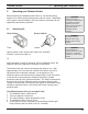
4 Installation 1. Install exhaust deflector on heater exhaust outlet or install exhaust pipe. 2. Route the exhaust system so that the possibility of discharged exhaust gasses entering the vehicle is prevented. 3. Direct the discharge opening of the exhaust system in such a way as not to be pointed in the direction of travel, and so located that the possibility of clogging caused by snow, mud or debris is prevented. 4. Any condensation water collecting in the exhaust pipe must be discharged.
Thermo 230/300 4.6 Plumbing Into the Coolant System 4.6.1 General Information An efficient heating system must have an adequate supply of hot water to all heater cores. The amount of hot water available to a typical three or more heater core system depends on the water pumps capability and the amount of restriction within the coolant system. 4 Installation WARNING When working on the coolant system, allow the engine to cool down and open the radiator cap carefully.
4 Installation Thermo 230/300 Fig. 401: Series Plumbing Circuit (Shown with heater installed) B: Heater Cores arranged in Parallel (fig. 402) A parallel heating system works in this fashion: Heated water (coolant) from the engine travels through a common supply and return circuit, but unlike a series system, the heater cores are connected across the circuit at intervals along its length.
Thermo 230/300 C: Engine pre-heating and/or Boost Heating Only (fig. 403) This type of installation is used where engine pre-heating and or system boost heating is the primary requirement. The heater can be installed across the heating circuit before any of the vehicle heating cores or installed independently of the vehicles heating circuit by plumbing directly from and returning back into the engine.
4 4.6.3 Installation Example of a Heater Installation in a Bus Fig.
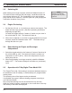
Thermo 230/300 4.7 Fuel System 4.7.1 General Description 4 Installation NOTE The heater is equipped with an internal self priming fuel pump. The fuel is drawn from the vehicles fuel tank through a fuel standpipe. This standpipe can be utilized on vehicles with a spare threaded port as shown in figure 405. The Webasto heater utilizes 37° flare JIC fuel connection fittings. The fuel supply line fitting is a JIC #4 and the return line is a JIC #6. 4.7.
4 Installation - use 1/4" or 1/2" spare port on fuel tank (if available) and install fuel standpipe securely in fuel tank, use pipe thread sealant on all pipe threads. 3. Route and secure fuel lines from heater to fuel tank. Route according to applicable regulations. Use grommets to protect fuel lines whenever routed through holes. 4. Connect fuel lines to fuel standpipe and heater using 1/4" (6 mm) I.D. fuel line.
Thermo 230/300 4.8 Wiring Connections 4.8.1 General Information The control unit is equipped with low voltage protection, therefore it is imperative to keep vehicle batteries in good condition. Thermo 230/300 heaters are available in 24 volt configurations only. 4.8.2 Timer and Switch Connections 4 Installation NOTE The Webasto heating system will not perform to your satisfaction with weak batteries.
Installation Wiring Diagram - with Switch X4 C A B BROWN RED 4.8.4 BLACK 4 Fig.
Thermo 230/300 Installation BLACK X4 C A B RED Wiring Diagram - with 7-Day Digital Timer Model 1531 BROWN 4.8.5 4 Fig.
4 4.9 Installation Thermo 230/300 Initial Operation 1. Check your installation for: - loose nuts and bolts. - exhaust pipe routing and clamp tightness. - loose hose clamps. - routing and securing of wiring and heater hoses. - kinked or pinched hoses. - battery connection and polarity. 2. Top off or refill cooling system with coolant as per engine manufacturers recommendations. 3. Open shut-off valves and driver’s heater valve. 4. Set vehicle heater controls to maximum heat position. 5.
Thermo 230/300 15. Complete the warranty card and send to Webasto Thermosystems (There is an area on the last page of this manual for recording information which is useful when calling for technical support). 16. Install the compartment cover if equipped. Installation is now complete. 4 Installation NOTE The engine temperature gauge may read a lower temperature depending on the location of the temperature sensor on the engine.
Thermo 230/300 5. Maintenance of the Heater 5.1 Annual Maintenance 5 Maintenance of the Heater The Webasto heater requires a minimum of maintenance to operate.
Thermo 230/300 6. Basic Troubleshooting 6.1 General Information 6 This section describes troubleshooting procedures for the Thermo 230/300 coolant heater. Troubleshooting is normally limited to the isolation of defective components.
6 6.2.1 Basic Troubleshooting Reading a Fault Code with 1531 “Comfort” Timer Installed Where the Thermo 230/300 installation includes the model 1531 “Comfort” Digital Timer, you will be able to read the current failure fault code directly from the timer display. The flame indicator symbol will “flash” the present fault code once and will then convert the fault code to an alphanumeric display message. For example: fault code 10 (overheat) will be visible on the timer display as “F 10".
Thermo 230/300 6.3 6 Basic Troubleshooting Operational Failure Symptoms via Fault/Flash Code The following table lists the possible faults which can be read by flashing code or read directly off of an appropriate timer or with the PC diagnostics kit. Failure Symptom Probable Cause Check and Correct 1X Flash (F 01) No combustion after completion of start up sequence.
6 6.4 Basic Troubleshooting Reading and Removing Fault Codes Stored in Memory with the Webasto PC Diagnostics Kit and Adapter It is possible to read and remove (reset) stored fault codes from the Thermo 230/300 memory. This is achieved through the use of a diagnostic interface kit connected to the Thermo 230/300 and an IBM compatible computer having the necessary software installed.
7 WARRANTY POLICY * Thermo 230/300 7. WARRANTY POLICY * Webasto Thermosystems Inc. and Webasto Thermosystems (Canada) Ltd., (herein after referred to as “Webasto”) warrants their products and related component parts against defects in materials and workmanship for 24 months effective from installation date or vehicle registration date for O.E.M. installations. The warranty period may not however, exceed 36 months from the original date of delivery by Webasto.
Webasto Product N.A., Inc. 15083 North Road Fenton, MI 48430 Technical Assistance Hotline USA: (800) 555-4518 Canada: (800) 667-8900 Org. 10/1998 Rev. 07/2012 P/N 907507 www.webasto.us www.techwebasto.