Webasto Thermo Test Version 2.
Thermo Test 1 1.1. 1.2. 1.3. 1.4. 1.5. 1.6. 1.7. General information/installation . . . . . . . . . . . . . . . . . . . . . 3 General . . . . . . . . . . . . . . . . . . . . . . . . . . . . . . . . . . . . . . . . . . 3 System requirements . . . . . . . . . . . . . . . . . . . . . . . . . . . . . . . . 6 Diagnostic-capable units . . . . . . . . . . . . . . . . . . . . . . . . . . . . . 7 OE-applications with W-Bus . . . . . . . . . . . . . . . . . . . . . . . . . . . 8 OE-applications with K-Line . . . . .
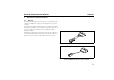
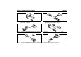
General information/installation 1 1.1. General General information/installation General The Webasto heater diagnostic software is used for checking heaters with a diagnostic capability in all voltage versions with the help of a personal computer. The PC diagnostic adapter and the type-specific test adapter supplied with the software are required to connect the heater to the PC (see fig. 1 up to 14). The test adapters are identical as used in combination with the diagnostic computer.
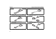
General General information/installation Fig. 3: Test adapter for BBW 46 S and DBW 46 S heaters. You can make an appropriate adapter yourself if required. Fig. 6: Test adapter for Air Top 3500/5000/ST and Air Top 2000 ST heaters, order no. 92555A Fig. 4: Test adapter for BW 80 and DW 80 heaters, order no. 21333A Fig. 7: Test adapter for DW 230/300/350 and Thermo 230/300/350 heaters, order no. 20865A Fig. 5: Test adapter for Thermo Top Z/C trade and Air Top 2000/S heaters, order no. 92566B Fig.
General information/installation Fig. 9: Test adapter for DW 230/300/350 and Thermo 230/300/350 heaters, order no. 88336A General Fig. 12: Test adapter for DW 230/300/350 and Thermo 230/300/350 (MB/Citaro) heaters, order no. 66265A Fig. 10: Test adapter for DW 230/300/350 and Thermo 230/300/350 (RVI) heaters, order no. 92629A Fig. 13: Test adapter for Thermo 230/300/350 Rail heaters, order no. 9012265C Fig. 11: Test adapter for DW 230/300/350 and Thermo 230/300/350 (Van Hool) heaters, order no.
System requirements 1.2. System requirements – 500 MHz processor or higher depending on the requirements of the operating system. – Min. 256 MB of RAM depending on the requirements of the operating system. – Microsoft Windows XP, Vista (32-Bit), Windows 7 (32-Bit). – 30 MB available space on the hard disk. – A vacant COM port (RS232C) or a vacant USB port. – Internet access (for software updates).
General information/installation 1.3. Diagnostic-capable units Diagnostic-capable units Heater selection for USB interface NOTE If the device is not listed in Select device, the heater must be a model with W-Bus. W-Bus-capable heaters are grouped under the heading of W-Bus. In this case use the W-Bus selection. The W-Bus selection contains a list of various heaters that use the same diagnostic port. (See also chapter 1.4.
OE-applications with W-Bus 1.4. General information/installation OE-applications with W-Bus PC-Diagnosis with W-Bus enables: • • • • • • • • • • • overview of heaters’ parameters and components; display error list (in case errors occur); delete error memory; heater information; graphs of actual values of components; overview heaters’ operating data; component test; fuel prime; CO2 calibration; Protocol of the measured values; creation of a summary.
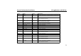
General information/installation OE-applications with W-Bus Brand Model Heater Diagnosis via… Audi A3, ABII TT-V PIN 2 of the control unit or via Telestart.Telestart is situated in the trunk. Audi A6, C6 TT-V PIN 2 of the control unit or via Telestart. Telestart is situated in the trunk. Audi A8, D3 TT-C PIN 1 of the control unit or via Telestart. Telestart is situated near the C-pillar. Audi A8, D3 TT-Z PIN 1 of the control unit.
OE-applications with W-Bus General information/installation Brand Model Heater Diagnosis via… Mercedes CLS, C209 from 11/2004 TT-C PIN 1 of the control unit or via Telestart. Telestart is situated in the trunk. Mercedes E Class, W211 TT-C PIN 1 of the control unit or via Telestart. Telestart is situated in the trunk. Mercedes G Class, G463 TT-C PIN 1 of the control unit or via Telestart. Telestart is situated in the trunk.
General information/installation OE-applications with W-Bus Brand Model Heater Diagnosis via… VW Passat, PQ46, starting 11/2004 TT-V PIN 2 of the control unit or via Telestart. VW Phaeton, D1 TT-C PIN 1 of the control unit or via Telestart. VW Phaeton, D1 TT-Z PIN 1 of the control unit. VW Touareg, Mac TT-C PIN 1 of the control unit or via Telestart. VW Touareg, Mac TT-Z PIN 1 of the control unit. VW Touran, PQ35 TT-V PIN 2 of the control unit.
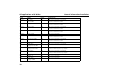
OE-applications with K-Line 1.5. General information/installation OE-applications with K-Line Vehicle specific, K-Line capable heaters have been summarised here. At device selection, please select the device specified in the column “device selection” of the table below. NOTE For PC-Diagnosis, a wire harness Diagnosis OEM (order no. 9016761A) is required. See fig. 15.
General information/installation OE-applications with K-Line Brand Model Heater Device selection Diagnosis via… Hyundai Trajet, F0 TT-Z TT-Z PSA Kia Sorento, BL TT-Z TT-Z PSA Lancia Thesis, 841 TT-C TT-Z/C Fiat Vehicle diagnosis plug (below steering column) or directly at PIN 2 of the control unit. Vehicle diagnosis plug (front fuse box) or directly at PIN 2 of the control unit. Vehicle diagnosis plug or directly at PIN 2 of the control unit.
Installation on the hard disk 1.6. General information/installation Installation on the hard disk NOTE Webasto does not accept liability for any data loss on your computer. Therefore, we recommend you back up your hard disk. If you already have older versions of the software installed on your computer, they must be uninstalled before the new installation.
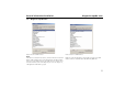
General information/installation Installation on the hard disk Webasto Thermo Test software. If you wish to change the specified path (C:\Program Files\WebastoThermoTest\), click “Browse” and select a different folder. Please note Please note that if you select your own path, any folders with the same name on the hard disk will be overwritten. 2. 4. Confirm the settings with “Next”. 5. The installation is completed. Close the window with "Close" Click “Next” to continue.
Installation on the hard disk 6. 7. 16 General information/installation After connecting the USB adapter the following message will be displayed: 8. Click "Install the software automatically (Recommended)" and confirm with “Next”. 9. Click “Finish” to complete installation of the USB drivers successfully. Click "No, not this time" and"Next", to proceed with the USB driver installation.
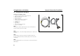
General information/installation 1.7. Connection Connection CAUTION The work MUST be completed in the following sequence! – Connect the 9-pin plug or the USB plug (both cables are supplied) to a vacant serial port (COM1 or COM2) or a vacant USB port on the PC (the plug can remain connected if necessary). – Connect the 9-pin plug or USB plug to the diagnostic adapter. NOTE The system must be switched manually between COM1 and COM2 (if the PC has more than one serial port).
Test procedure 2 2.1. Heater-specific diagnosis Heater-specific diagnosis Test procedure NOTE The heater must be connected to the vehicle’s electrical system but not necessarily operating to execute a test function. Thermo Top 98: When using USB diagnosis adapter ID 9008487B, test adapter ID 92566B is required. If the adapter is not connected or connected to the wrong port or the heater is not on or not properly connected, an error message will be displayed. In this case check the above causes.
Heater-specific diagnosis 2.2. Menu: Diagnosis Menu: Diagnosis 2.2.1. Select device (Start diagnosis) Open the dialogue box to select the control unit using the Diagnosis / Select device menu command or by clicking the button .
Menu: Diagnosis Heater-specific diagnosis 2.2.4. Component test Open the dialogue box of the same name using the Diagnosis / Component test… menu command or by clicking the button. NOTE The priming process cannot be stopped on some heaters. • Mark the components that you wish to test in the options box, for example the combustion air fan. • Click the button to start the test on the selected component. • Click the button to terminate the current test. 2.2.6.
Heater-specific diagnosis Analysis 1. Compare the fuel quantity in the metering box with the set point value of 20 ml (+/- 2 ml). 2. When there are deviations from the set point value, disconnect the fuel pump from the vehicle’s fuel tank. CAUTION Remove fuel tank cap, relief pressure, close fuel tank. Collect fuel that runs out in a suitable container and respectively close fuel line with an appropriate tool.
Menu: Diagnosis 2.2.8. Open summary To open an existing summary of diagnostic data, open the report file dialogue box using the Diagnosis / Open summary... menu command. • Mark the file you want to review by clicking it. The name of the marked file will be transferred into the file name box. • Click the button or double click the file name to open the text file. • The Display summary view will be opened. • Click the button to close the view. 2.2.9.
Heater-specific diagnosis 2.3. Menu: View Menu: View You can select between different views in order to see different displays and data about the heaters: • Use the View / Trend graphic... menu command or click the to open the trend graphic. 2.3.1. Overview window This view gives you an overview on the values during the diagnosis. In addition to the operating voltage, temperature, etc. the device status is also shown. 2.3.5.
Menu: Error memory 2.4. Menu: Error memory 2.4.1. Display error lists • Use the Error memory / display error list... menu command or click the button to open the Error display window. • This view displays a list of all the errors saved in the control unit together with the values that occurred during the error. Each error is listed separately to distinguish clearly between them. • If you click an error, an explanation of that error will be displayed. 2.4.2.
Heater-specific diagnosis 2.5. Menu: Print Menu: Print 2.5.1. Print report To print a summary select the Print / Report menu command, the F12 function key, or by clicking the button.
Menu: Control (depending on heater version) 2.6. Menu: Control (depending on heater version) 2.6.1. Off To switch off the heater select the Control / Heater off menu command, the F4 function key, or by clicking the button. 2.6.2. On To switch on the heater select the Control / Heater on menu command or click the button. 2.6.3. Parking heating If you wish to use parking heating mode select the Control / parking heating mode or click the button. 2.6.4.
Heater-specific diagnosis 2.7. Menu: Calibration Menu: Calibration 2.7.1. CO2 adjustment To carry out the calibration process select the Calibration / CO2 adjustment or by clicking the button. NOTE This function is only available when the heater is in certain statuses.
Menu: Tools 2.8. Menu: Tools NOTE If the diagnostic adapter is connected to the USB port, it will be automatically recognised by Windows. No settings are required. The Tools menu provides you with two menu commands to configure your computer: 2.8.1. COM port • Open the COM port selection dialogue box using the Tools / COM port menu command. • Select the COM port (COM1 or COM2) you want to use to connect to the external device. • Click the button to confirm your selection.
Heater-specific diagnosis 2.9. Menu: Window Menu: Window The Window menu enables you to influence how open dialogue boxes and view windows are displayed: 2.9.1. Overlapping Select the Window / overlapping menu command if you want open windows to be arranged overlapping each other. 2.9.2. Side-by-side Select the Window / Side-by-side menu command if you want open windows to be of the same size and arranged next to each other without any overlap. 2.9.3.
Menu: Help 2.10. Menu: Help 2.10.1. Help This menu displays help topics relating to this diagnostic software. • To obtain help on the program and problems, select the Help / Help menu command or click the button . From this window you can go to instructions that will give you a step by step guide to using Webasto Thermo Test 2002 or you can view various types of reference information. • As soon as you have opened the help topic you can click the Contents button at any time to return to the contents window.
Service modules for components and accessories 3 3.1. 3.1.1. IPCU intelligent PWM control unit Service modules for components and accessories IPCU intelligent PWM control unit IPCU programming The button “Set selected parameters” sets the predefined parameter for the selected vehicle module under “IPCU programming”. The parameter values can also be changed individually. Programming the selected parameters is not carried out until the "Program IPCU" button is pressed.
IPMU Intelligent PWM Master Unit 3.2. 3.2.1. Service modules for components and accessories IPMU Intelligent PWM Master Unit Reading out vehicle specific parameters via IPMU In case the correct vehicle specific parameters for programming the IPCU module are unknown, these can be read out via a IPMU module and special measuring equipment.After the IPMU module is connected to the USB Diagnostics Adapter and to the vehicle with measuring equipment, reading out can be started with the this dialogue box.
Service modules for components and accessories 3.3. 3.3.1. Telestart T100 HTM Telestart T100 HTM Programming the system level Heating Time Management (HTM) in the Telestart receiver calculates the heating duration depending on the prevailing temperature and the comfort level (C1 to C5) selected using the hand-held transmitter. Comfort level We recommend comfort level 2/3 as the basic setting.
General 4 4.1. Troubleshooting General When you select a test function, an error message is displayed. • Check if the diagnostic adapter is connected to the selected serial port or the USB port on the PC and that heater is properly connected. • Check whether the heater is switched on and is receiving power.
National: Hotline: 01805 93 22 78 (€ 0,14 aus dem deutschen Festnetz) Hotfax: 0395 5592 353 Hotmail: technikcenter@webasto.com www.webasto.de International: www.webasto.com http://dealers.webasto.