Th23_EA_degbfr_g.book Seite I Dienstag, 15.
Th23_EA_degbfr_g.book Seite III Dienstag, 15. Februar 2005 2:03 14 Thermo 230/231/300/301/350 Improper installation or repair of \/Vebasto heating and cooling systems can cause fire or the leakage of deadly carbon monoxide leading to serious injury or death. To install and repair Webasto heating and cooling systerns you need to have completed a Webasto training course and have the appropriate technical documentation, special tools and special equipment.
Th23_EA_degbfr_g.book Seite IV Dienstag, 15. Februar 2005 2:03 14 Thermo 230/231/300/301/350 Inhaltsverzeichnis Contents 1 2 3 4 5 6 7 8 9 10 11 12 13 14 1 2 3 4 5 6 7 8 9 10 11 12 13 14 Gesetzliche Bestimmungen für den Einbau . . . . . . . . . . . . 1 Verwendung / Ausführung . . . . . . . . . . . . . . . . . . . . . . . . . . 3 Einbau . . . . . . . . . . . . . . . . . . . . . . . . . . . . . . . . . . . . . . . . . . 4 Einbaubeispiel für Thermo 230/300/350 . . . . . . . . . . . . . .
Th23_EA_degbfr_g.book Seite 35 Dienstag, 15. Februar 2005 2:03 14 Thermo 230/231/300/301/350 1 Statutory regulations governing installation Statutory regulations governing installation 1.1.
Th23_EA_degbfr_g.book Seite 36 Dienstag, 15. Februar 2005 2:03 14 Statutory regulations governing installation 2.4. Exhaust system 2.4.1.The exhaust outlet must be positioned in such a way that exhaust fumes cannot get into the interior of the vehicle through ventilation devices, hot-air inlets or open windows. 2.5. Combustion air inlet 2.5.1.The air for the combustion chamber of the heater must not be extracted from the passenger cabin of the vehicle. 2.5.2.
Th23_EA_degbfr_g.book Seite 37 Dienstag, 15. Februar 2005 2:03 14 Thermo 230/231/300/301/350 2 Use / version Use / version 2.1. Use of the water heaters The Webasto Thermo 230/231/300/301/350 water heaters are used in connection with the vehicle's own heating system 2.2. – to heat the passenger cabin, – to defrost the vehicle windows and – to preheat water-cooled engines.
Th23_EA_degbfr_g.book Seite 38 Dienstag, 15. Februar 2005 2:03 14 Installation 3 Installation IMPORTANT – The statutory regulations governing installation on pages 35 and 36 must be adhered to. – If the water heater is to be operated in a separately installed heating system, prior to installation an installation planning report must always be submitted to Webasto for approval. If this approval is not obtained, all warranty and liability claims will be void.
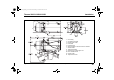
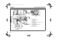
Th23_EA_degbfr_g.book Seite 39 Dienstag, 15. Februar 2005 2:03 14 Thermo 230/231/300/301/350 Installation 1 2 3 4 6 7 8 12 11 9 1 2 3 4 5 6 7 8 9 10 11 12 5 CO2 setting Combustion air intake Exhaust fume outlet Fuel intake Fuel discharge Space required to remove the burner chamber Coolant intake Temperature limiter Swivel range, at least approx. 25° Max. swivelled burner Coolant outlet Temperature sensor 10 Fig.
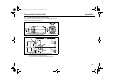
Th23_EA_degbfr_g.book Seite 40 Dienstag, 15. Februar 2005 2:03 14 Installation Thermo 230/231/300/301/350 610 1 415 ø38 ca 226 2 3 6 ca.440 26,5 4 302,5 382 ø70,3 ca.160 5 7 8 ca.145 200 12 11 ca. 25° ca.440 9 10 Fig.
Th23_EA_degbfr_g.book Seite 41 Dienstag, 15. Februar 2005 2:03 14 Thermo 230/231/300/301/350 Installation 3.2. To install the Thermo 230 / 300 / 350 heater The heater may be secured either with four screws M8 (Figure 4/1) or with four screws and nuts (Figure 4/2). Fig. 3: Horizontal installation position 1 1 2 2 2 2 Fig. 4: 1 D 1 Hole pattern for Thermo 230 / 300 / 350 heater 4.5 mm diameter for using M4 screws, 2.9 mm diameter for using B3.
Th23_EA_degbfr_g.book Seite 42 Dienstag, 15. Februar 2005 2:03 14 Installation Thermo 230/231/300/301/350 2 4 6 9 5 7 3 10 12 11 8 Fig. 5: 42 Dimensions of the Thermo 231 / 301 heater (vertical installation) 1 1 2 3 4 5 6 7 8 9 10 11 12 CO2 setting Combustion air intake Exhaust fume outlet Fuel intake Fuel discharge Space required to remove the burner chamber Coolant intake Temperature limiter Swivel range, at least approx. 25° Max.
Th23_EA_degbfr_g.book Seite 43 Dienstag, 15. Februar 2005 2:03 14 Thermo 230/231/300/301/350 Installation 3.3. To install the Thermo 231 / 301 heater The heater is to be secured with four M8 screws (Figure 7), body washers and nuts. IMPORTANT The heat transfer base must be supported on a stable surface connected to the floor of the car. The securing screws are designed to fix the heater in position, not to suspend it. Fig. 7: Fig.
Th23_EA_degbfr_g.book Seite 44 Dienstag, 15. Februar 2005 2:03 14 Installation 3.4. Model plate The model plate must be protected from damage and must be clearly legible when the heater is installed (otherwise a duplicate model plate must be used). Thermo 230/231/300/301/350 3.5. Additional Type Plate Heaters approved for use in rail vehicles are additionally identified by the type plate illustrated below: Feel the drive Eisenbahn-BundesamtBauartzulassung Nr: EBA 32AZ3/0141/04 Fig.
Th23_EA_degbfr_g.book Seite 45 Dienstag, 15.
Th23_EA_degbfr_g.book Seite 46 Dienstag, 15. Februar 2005 2:03 14 To install the circulating pump 5 Thermo 230/231/300/301/350 To install the circulating pump The circulating pump must be installed as shown in Figures 11 and 12, Figure 14 and 15, Figure 17 and 18 or Figures 20 and 21. Note the installation position. NOTE: The pump ports and connection lines from the water intake and water outlet must be flush (no stress). 5.1. U 4814 circulating pump Fig.
Th23_EA_degbfr_g.book Seite 47 Dienstag, 15. Februar 2005 2:03 14 Thermo 230/231/300/301/350 5.2. To install the circulating pump Aquavent 5000 S circulating pump 99,5 249 53 60 32 131,5 38 31 38 23 110 225 Br- Sw+ 0-90° 90° Fig. 14: Aquavent 5000 S circulating pump Installation position Fig. 15: Hole pattern for the stand for Aquavent 5000 S circulating pump Delivery rate (with water at 20°C) Flow resistance (with the pump stopped) Fig.
Th23_EA_degbfr_g.book Seite 48 Dienstag, 15. Februar 2005 2:03 14 To install the circulating pump 5.3. Thermo 230/231/300/301/350 U 4851 circulating pump 279 115 53 60 32 31 500 38 38 23 110 63 6,5 24 100 * 90° 0-90° * Clamping area of the stand clamp Fig. 17: U 4851 circulating pump Installation position 85 97,5 Br- Sw+ Fig. 18: Hole pattern for the stand for U 4851 circulating pump Delivery rate (with water at 20°C) Flow resistance (with the pump stopped) Fig.
Th23_EA_degbfr_g.book Seite 49 Dienstag, 15. Februar 2005 2:03 14 Thermo 230/231/300/301/350 5.4. To install the circulating pump Aquavent 6000 S circulating pump 284 53 115 180,5 60 32 31 500 38 38 23 110 63 0-90° 6,5 24 100 * 85 90° 97,5 Br- Sw+ 122,5 Fig. 21: Hole pattern for the stand for the Aquavent 6000 S circulating pump * Clamping area of the stand clamp Fig.
Th23_EA_degbfr_g.book Seite 50 Dienstag, 15. Februar 2005 2:03 14 To install the circulating pump 5.5. Motor for the U 4851 / Aquavent 6000 S circulating pump The U 4851 / Aquavent 6000 S circulating motor is fitted with a brushless motor. 5.5.1. Soft start The motor starts slowly to protect its material. It does not reach its maximum speed for approx. 5 seconds. 5.5.2. Dry running protection (U 4851 only) A dry running protection is integrated in the motor for speeds >3300 rpm.
Th23_EA_degbfr_g.book Seite 51 Dienstag, 15. Februar 2005 2:03 14 Thermo 230/231/300/301/350 6 Connection to the vehicle cooling system Connection to the vehicle cooling system The heater is connected to the vehicle cooling system as shown in Figures 1, 2, 5 and 10. The system must contain at least 10 litres of coolant. A minimum of 20% of a good quality antifreeze should be maintained in the heating circuit of the heater at all times. The water hoses supplied by Webasto must always be used.
Th23_EA_degbfr_g.book Seite 52 Dienstag, 15. Februar 2005 2:03 14 Fuel supply 7 Fuel supply The fuel is taken from the vehicle fuel tank or from a separate fuel tank. 7.1. Fuel lines Fuel lines are to be installed with a gradient wherever possible to prevent air inclusions. Connections within the line are to be secured with hose clips if no mechanical screw connectors are used. If fuel hoses are used, the hoses supplied by or available from Webasto must generally be used.
Th23_EA_degbfr_g.book Seite 53 Dienstag, 15. Februar 2005 2:03 14 Thermo 230/231/300/301/350 8 Combustion air supply Combustion air supply Under no circumstances may the combustion air be taken from areas occupied by people. The combustion air intake opening must not point in the direction of travel. It must be located so that it cannot become clogged with dirt or snow and cannot suck in splashing water.
Th23_EA_degbfr_g.book Seite 54 Dienstag, 15. Februar 2005 2:03 14 Exhaust pipe 9 Exhaust pipe The opening of the exhaust pipe must not point towards the front of the vehicle. The exhaust pipe opening must be located so that it cannot become clogged with snow and mud. Rigid pipes of unalloyed or alloyed steel with a minimum wall thickness of 1.0 mm or flexible piping of alloyed steel only must be used as exhaust line. The exhaust pipe is secured to the heater using a clamping collar, for example.
Th23_EA_degbfr_g.book Seite 55 Dienstag, 15. Februar 2005 2:03 14 Thermo 230/231/300/301/350 10 Electrical connections Electrical connections 10.1. Heater connection IMPORTANT HIGH VOLTAGE: Danger of death. Disconnect the plug connection to the vehicle before you open the heater.
Th23_EA_degbfr_g.book Seite 56 Dienstag, 15. Februar 2005 2:03 14 Electrical connections Thermo 230/231/300/301/350 10.5. Water Temperature Control Thresholds:: Heater Auxiliary heating 0->1 1->control idle period Thermo 230.032 Thermo 300.031 Thermo 350.032 Thermo 230.126 Rail Thermo 300.126 Rail Thermo 350.126 Rail 10.5.1.
Th23_EA_degbfr_g.book Seite 57 Dienstag, 15. Februar 2005 2:03 14 Thermo 230/231/300/301/350 10.6. Legend for circuit diagrams ➀ Diagnostic connector ➁ ➂ Digital timer P: with positive at connection 10= Continuous operation with immediate heating Connection 10 open = Variable heating duration can be programmed (10 min to 120 min); Default setting 120 min Plug assignment: Plug assignment D1 D2 D3 D4 F1 F2 ➃ ➄ 4-core cable 0.75 gr 0.75 or 0.75 gn 0.75 br Not occupied Not occupied 7-core cable 0.
Th23_EA_degbfr_g.book Seite 58 Dienstag, 15.
Th23_EA_degbfr_g.book Seite 59 Dienstag, 15.
Th23_EA_degbfr_g.book Seite 60 Dienstag, 15.
Th23_EA_degbfr_g.book Seite 61 Dienstag, 15. Februar 2005 2:03 14 Thermo 230/231/300/301/350 Electrical connections Fig.
Th23_EA_degbfr_g.book Seite 62 Dienstag, 15. Februar 2005 2:03 14 Starting the heater for the first time 11 Starting the heater for the first time NOTE: Refer to the safety instructions in the operating and maintenance instructions. The operating and maintenance instructions must be read through without fail before starting the heater. After you have installed the heater, bleed the water system and the fuel supply system carefully.
Th23_EA_degbfr_g.book Seite 63 Dienstag, 15. Februar 2005 2:03 14 Thermo 230/231/300/301/350 12 Maintenance Maintenance Periodic service activities have to be performed in accordance with Chapter 8 and Appendix A of the Workshop Manual. When the heater is operated in rail vehicles, maintenance chart / test certificate item no. 90 087 22 is to be used.
Th23_EA_degbfr_g.book Seite 64 Dienstag, 15. Februar 2005 2:03 14 Troubleshooting 13 Troubleshooting 13.1. Fault lock-out If it recognises one of the following fault features, the heater will conduct a fault lock-out. If several fault lock-outs occur in sequence, the heater will be disabled. Flashing pulse signals are output by the operation indicator light for heaters with control module 1572D. The combustion air blower and the circulating pump will be shut down after approx. 120 seconds. 13.1.1.
Th23_EA_degbfr_g.book Seite 65 Dienstag, 15. Februar 2005 2:03 14 Thermo 230/231/300/301/350 13.2. Fault code output on heaters with control module 1572D If the system is equipped with a standard timer, a fault message appears on the display of the timer after a fault occurs. Troubleshooting 13.2.1. To reset the heater after a fault lock-out To reset the heater after a fault lock-out, switch on the heater and cut the power supply to it during the starting process.
Th23_EA_degbfr_g.book Seite 66 Dienstag, 15. Februar 2005 2:03 14 Technical data 14 Technical data Except where limit values are specified, these technical data refer to the usual heater tolerances of ± 10% at an ambient temperature of +20°C and at the rated voltage. NOTE: The assignment of circulating pumps to heaters must be made using the water-side resistors. 14.1. Fuel The diesel fuel specified by the manufacturer must be used.
Th23_EA_degbfr_g.book Seite 67 Dienstag, 15. Februar 2005 2:03 14 Thermo 230/231/300/301/350 Heater Type EC type approval number Model Heating flow Technical data e1*2001/56* kW (kcal/h) Fuel Fuel consumption kg/h Rated voltage VOperating voltage range VRated power consumption (without circulating pump)W Max. ambient temperature during operation (Heater, control module, circulating pump) C° Max. storage temperature (control module) C° Max.
Th23_EA_degbfr_g.book Seite 68 Dienstag, 15. Februar 2005 2:03 14 Technical data Thermo 230/231/300/301/350 Circulating pump Delivery rate Rated voltage Operating voltage range Rated power consumption Dimensions (Tolerance ± 3 mm) I/h VVW mm mm mm kg Weight U 4814 5200 (against 0.15 bar) 24 20...28 104 Length 228.