Wasserheizgeräte Water Heaters Chauffages à eau Einbauanweisung Installation Instructions Instructions de montage Thermo 90 S Thermo 90 ST Thermo 90 S Thermo 90 S Thermo 90 S-ADR 05/2008 1301494C (Benzin) (Petrol) (Essence) (Diesel) (Gas-oil) (Gefahrguttransport) (Transport of hazardous goods) (Transport de marchandises dangereuses) Thermo 90 ST (Benzin) (Petrol) (Essence) Thermo 90 ST (Diesel) (Gas-oil) Thermo 90 ST-ADR (Gefahrguttransport) (Transport of hazardous goods) (Transport de marchandises dang
Das unsachgemäße Einbauen oder Reparieren von Webasto Heiz- und Kühlsystemen kann Feuer verursachen oder zum Austritt von tödlichem Kohlenmonoxid führen. Dadurch können schwere oder tödliche Verletzungen hervorgerufen werden. Für den Einbau und die Reparatur von Webasto Heiz- und Kühlsystemen bedarf es eines Webastotrainings, technischer Dokumentation, Spezialwerkzeuge und einer Spezialausrüstung.
La réparation ou l’installation impropre des systèmes de chauffage et de refroidissement Webasto peut conduire à l’incendie de l’appareil ou encore à des fuites mortelles de monoxyde de carbone pouvant entraîner de graves lésions voire même la mort. Pou l’installation ou la réparation des systèmes de chauffage ou de refroidissement Webasto, il est nécessaire d’avoir une formation Webasto, une documentation technique, des outils spécifique et des équipements particuliers.
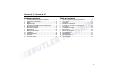
Thermo 90 S / Thermo 90 ST Inhaltsverzeichnis Table of contents 1 2 3 4 5 6 7 8 9 10 11 12 13 1 2 3 4 5 6 7 8 9 10 11 12 13 Gesetzliche Bestimmungen für den Einbau ´ . . . . . . . . . . . 1 Verwendung / Ausführung . . . . . . . . . . . . . . . . . . . . . . . . . . 4 Einbau . . . . . . . . . . . . . . . . . . . . . . . . . . . . . . . . . . . . . . . . . . 5 Einbaubeispiele . . . . . . . . . . . . . . . . . . . . . . . . . . . . . . . . . . . 6 Anschluss an das Kühlsystem des Fahrzeuges . . . . . . . .
Thermo 90 S / Thermo 90 ST 1 Statutory regulations governing installation Statutory regulations governing installation 1.1.
Statutory regulations governing installation 2.2.5 Every reasonable precaution should be taken in positioning the heater to minimise the risk of injury and damage to personal property. 2.3. Fuel supply 2.3.1. The fuel filler must not be situated in the passenger compartment and must be provided with an effective cap to prevent fuel spillage. 2.3.2. In the case of liquid fuel heaters, where a supply separate to that of the vehicle is provided, the type of fuel and its filler point must be clearly labelled.
Thermo 90 S / Thermo 90 ST Statutory regulations governing installation (Extract from Directive 2001/56/EC Annex IX) 3. Technical specifications for heater units for installation in dangerous goods transporters (Annex 9) 3.1. General (EX/II, EX/III, AT, FL and OX vehicles) 3.1.1. The combustion heaters and their exhaust gas routing shall be designed, located, protected or covered so as to prevent any unacceptable risk of heating or ignition of the load.
Use / version 2 Thermo 90 S / Thermo 90 ST Use / version 2.1. Use of the water heaters The Webasto water heater is used in connection with the vehicle's own heating system – to heat the cab, – to defrost the vehicle windows and – to preheat water-cooled engines. The water heater operates independently of the engine and is connected to the cooling system, the fuel system and the electrical system of the vehicle.
Thermo 90 S / Thermo 90 ST 3 Installation Installation IMPORTANT – The water heater must be installed outside the passenger cabin. – The requirements of the latest version of the ADR must also be observed for the installing the heater into vehicles used to transport hazardous substances. NOTE: If the vehicle manufacturer has issued instructions, they must be followed. 3.2. To install the heater The heater must be secured with at least three M8 screws. The screws must be tightened with a torque of 18 Nm.
Examples for installation 4 Thermo 90 S / Thermo 90 ST Examples for installation Wiring harness Fuel line Exhaust line Water circuit Fig.
Thermo 90 S / Thermo 90 ST 5 Connection to the vehicle cooling system Connection to the vehicle cooling system In thermostat circuits, only use thermostats which start to open at < 65 °C. The heater is connected to the vehicle cooling system as shown in Figure 2. The system must contain at least 6 litres of coolant. The water hoses supplied by Webasto must always be used. If you do not use these hoses, the hoses that you do use must comply with DIN 73411.
Fuel supply 6 Thermo 90 S / Thermo 90 ST Fuel supply The fuel is taken from the vehicle fuel tank or from a separate fuel tank. The values for the maximum pressure at the fuel extraction point are shown in the table below. Permissible fuel inflow height H (m) At max. pressure (bar) in fuel line 0.00 0.2 1.00 0.11 2.00 0.03 Maximum fuel intake height S (m) At max. negative pressure (bar) in the fuel tank 0.00 -0.10 0.50 -0.06 1.00 -0.
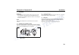
Thermo 90 S / Thermo 90 ST Fuel supply 6.1. Vehicles with diesel engines The fuel must be taken from the vehicle fuel tank or from a separate tank (see Figs. 4, 5 and 6). Fuel extractor Plastic tank Sealing ring Sealing ring Fig. 5: Tank fittings Fuel pickup from the plastic tank (Pickup via tank drain screw) Hole pattern Only use a tank connector if the fuel tank is made from metal Fig.
Fuel supply Thermo 90 S / Thermo 90 ST 6.2. Vehicles with petrol engines The heater must be integrated into the return line of fuel systems in carburettor and injection engines with a return line. In carburettor engines without a return line the heater must be integrated into the fuel system in the supply line between the fuel tank and the vehicle pump. NOTE A fuel feed line can normally be identified by the fact that a fuel filter is installed in it.
Thermo 90 S / Thermo 90 ST Fuel supply NOTE: Cut Mecanyl lines without burr and do not crush them. Do not cut them with side-cutting pliers. Correct Clip Since the lines normally cannot be routed with a constant rising gradient, the internal diameter must not be allowed to exceed a certain size. Air or gas bubbles will accumulate in lines with an internal diameter of more than 4 mm and these will cause malfunctions if the lines sag or are routed downwards.
Fuel supply Thermo 90 S / Thermo 90 ST 12 V and 24 V – diesel only 0° - 90° Fig. 11: Fuel filter Fig. 10: Metering pump 30.2 Horizontal installation position The pump should ideally be installed near the tank. 6.4.2. Installation and attachment The metering pump must be secured with a vibration-damping mounting. Its installation position is limited as shown in Figs. 9 and 10 in order to ensure effective auto-bleeding. 6.5. Fuel filter Only a Webasto filter, order no.
Thermo 90 S / Thermo 90 ST 7 Combustion air supply Combustion air supply Under no circumstances may the combustion air be taken from areas occupied by people. The combustion air intake opening must not point in the direction of travel. It must be located so that it cannot become clogged with dirt or snow and cannot suck in splashing water. The combustion air intake line (internal diameter at least 30 mm) may be 0.5 m to 5 m long with several bends totalling 360°. The minimum bending radius is 45 mm.
Exhaust pipe 8 Thermo 90 S / Thermo 90 ST Exhaust pipe The exhaust pipe (internal diameter 38 mm) can be installed with a length of 0.5 m to 5 m and several bends (360° altogether, minimum bending radius 85 mm). The exhaust silencer is essential and must be installed near the heater. The opening of the exhaust pipe must not point towards the front of the vehicle (see Figure 12).
Thermo 90 S / Thermo 90 ST 9 Electrical connections Electrical connections 9.1. Control module / heater connection The electrical connection of the heaters is made as shown in the circuit diagrams in Figures 15, 16, 17, 18, 19, 20, 21 and 22. Connection when installing Thermo 90 S-ADR and Thermo 90 ST-ADR in a hazchem vehicle (ADR) To install the Thermo 90 S-ADR and Thermo 90 ST-ADR heaters in hazchem vehicles, the requirements of ADR/RID part 9 para. 9.2.4.
Electrical connections 9.5. Thermo 90 S control module The control module offers protection type IP6K4K if it is installed in the position shown in Figure 13. Thermo 90 S / Thermo 90 ST 9.7.
Thermo 90 S / Thermo 90 ST 10 Circuit diagrams Circuit diagrams 10.1. Circuit diagram legend for the Thermo 90 S and Thermo 90 ST 1 Temperature coding (temperature at water outlet): See table on page 50 2 Digital timer P2: with positive at connection 10 = Continuous operation with immediate heating Connection 10 open = Variable heating duration can be programmed (10 min to 120 min); default setting 120 min 3 Vehicle fuse 4 Vehicle blower switch Cable cross-sections < 7.5 m 0.75 mm Cable colours 7.
Circuit diagrams Thermo 90 S / Thermo 90 ST 10.2. Thermo 90 S circuit diagram legend Item A1 A2 B1 B2 B3 B4 E F1 F2 F3 H1 H2 H3 H5 Designation Heater Control module Flame sensor Temperature sensor Temperature limiter/ Overheating guard Room thermostat Glow plug Fuse 20 A Fuse 5 A Fuse 20 A “Heating” symbol in the display Light max. 2 W Symbol light Lamp, min. 1.
Thermo 90 S / Thermo 90 ST Circuit diagrams ϑ ϑ Fig.
Circuit diagrams E B3 X1 B2 Thermo 90 S / Thermo 90 ST X1 1 2 3 X5 X3 4 5 X11 (ST 1) X6 X12 (ST 2) X13 (ST 3) 6 1 2 M1 M2 3 11 6 B1 12 11 10 9 8 9 7 1 12 9 2 2 11 7 1 5 3 58 15 9 2 7 5 1 3 1 58 15 30 30 X12 (ST 2) 2 12 5 2 3 11 7 6 10 gn/ws rt/bl 2 1 X13 (ST 3) bl gn 87a 9 12 or 87 4 or 86 8 X11 (ST 1) K3 rt 86 br 1 5 10 vi/bl 9 gr X3 87 87a K5 85 30 85 sw 30 sw br S8 2 A2 11 4 ge 7 br 12 B4 7 4 H6 vi ws 6 3
Thermo 90 S / Thermo 90 ST Circuit diagrams ϑ ϑ Fig.
Circuit diagrams Thermo 90 S / Thermo 90 ST ϑ ϑ Fig.
Thermo 90 S / Thermo 90 ST Circuit diagrams 10.3.
Circuit diagrams Thermo 90 S / Thermo 90 ST Fig.
Thermo 90 S / Thermo 90 ST Circuit diagrams Fig.
Circuit diagrams Thermo 90 S / Thermo 90 ST Fig.
Thermo 90 S / Thermo 90 ST Circuit diagrams Fig.
Initial start-up 11 Initial start-up NOTE: Refer to the safety instructions in the operating and maintenance instructions. The operating and maintenance instructions must be read through without fail before starting the heater. After you have installed the heater, bleed the water system and the fuel supply system carefully. Follow the instructions supplied by the vehicle manufacturer for this purpose.
Thermo 90 S / Thermo 90 ST 12 Troubleshooting Troubleshooting 12.1. Fault lock-out Fuel is supplied for max. 240 seconds if the flame does not start to burn. Fuel is supplied for max. 240 seconds if the flame goes out during operation. 12.2. Diagnostic after a fault lock-out for the Thermo 90 S and Thermo 90 ST Check the fuses and plug connectors. The fuel supply is shut off if the system overheats (temperature limiter is tripped). 12.2.1.
Troubleshooting 12.2.2. Version with switch If the system is operated with a switch, the nature of the fault is indicated by a flashing code on an indicator light during the run-on time of the heater.
Thermo 90 S / Thermo 90 ST 13 Technical data Technical data Except where limit values are specified, the technical data on the right refer to the usual heater tolerances of ± 10 % at an ambient temperature of + 20 °C and at nominal voltage. 13.1. Electrical components: The control module, motors for combustion air blower and circulating pump, glow plug, switch and timer (no timer for ADR mode) are designed for either 12 V or 24 V.
Technical data Heater EC licensing symbol Model Heat output Fuel Fuel consumption Rated voltage Operating voltage range Nominal power consumption with circulation pump (without vehicle fan) Max. ambient temperature: Heater: - Operation - Storage Control module:- Operation - Storage Metering pump: - Operation - Storage Max. operating pressure (heat medium) Capacity of the heat exchanger Max. combustion air intake temperature Minimum capacity of the system Delivery rate of the circulating pump against 0.
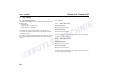
Thermo 90 S / Thermo 90 ST 3 Thermo 90 S ø20 Technical data 45 5 ø39 29 ø5 ø6,5 100 99 78 88 126 134 120 89 95 1 2 3 4 5 Combustion air intake Exhaust fume outlet Fuel intake Coolant intake Coolant outlet 4 ø30 1 2 ø20 ø38 48,6 98,6 = = 137,1 ø74 100 355 384 131 Thermo 90 ST 5 3 ø20 45 ø39 ø5 99 92 152 88 89 95 4 1 ø20 2 1 2 3 4 5 Combustion air intake Exhaust fume outlet Fuel intake Coolant intake Coolant outlet ø38 ø30 99 137 49 = = ø74 100 352 381 131
http://dealers.webasto.com http://www.webasto.com In multilingual versions the German language is binding. Änderungen vorbehalten Subject to modification Sous réserve de modifications Dans le cas d'une version rédigée en plusieurs langues, l'allemand est alors la langue qui fait foi. © 2007 All Rights Reserved Im Fall einer mehrsprachigen Version ist Deutsch verbindlich. IDENT.-NR.