Water Heaters Installation Instructions Thermo 90 Thermo 90-TRS Thermo 90 S Thermo 90 S-TRS (Transport of hazardous goods) Type BW 80 (Petrol), Type Thermo 90 S B (Petrol) Type DW 80 (Diesel), Type Thermo 90 S D (Diesel) Operating Instructions must be read before attempting to start up the heater.
Thermo 90 / Thermo 90 S Table of Contents Page Installation Instructions 1 Legal Provisions for Installation 1 Installation 2 Installation Example 3 Connection to the Vehicle’s Cooling System 4 Fuel Supply 4 Fuel Lines 6 Metering Pump 6 Combustion Air Supply 7 Exhaust Pipe 7 Electrical Connections 8 Circuit Diagrams 10 Initial Operation 17 Malfunctions 18 Technical Data 20 Variants 21 Template for heater mounting bracket 23 Webasto Service Phone Line 25 I
Thermo 90 / Thermo 90 S Installation Instructions Legal Provisions for Installation For testing the heater in accordance with articles 19, 20 oder 21 StVZO the following regulations are primarily to be observed (§ 22 a StVZO): NOTE: These provisions are binding within the scope of the StVZO (German Road Licensing Regulations) and should also be observed in countries where no special locally applicable regulations are in effect! Within the scope of the StVZO (German Road Licensing Regulations) “General Desig
Thermo 90 / Thermo 90 S Installation Thermo 90 5 3 CAUTION: - The legal provisions on page 1, relating to the installation of the heater, must be observed - When installing the Thermo 90-TRS in vehicles designed for the transport of hazardous materials the requirements laid down in TRS 002 and TRS 003 (Technical Guidelines relating to the ordinance of transporting hazardous goods on the road) must be fulfilled in addition to those of the StVZO.
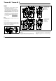
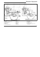
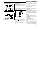
Thermo 90 / Thermo 90 S cable harness fuel line exhaust pipe water circuit without non-return valve Fig. 3: with non-return valve and thermostat Installation Examples for the Thermo 90 / Thermo 90 S Heater Legend of Fig.
Thermo 90 / Thermo 90 S Connection to the Vehicle Cooling System Fuel Supply In the case of thermostat circuits only thermostats that open at temperatures < 65°C should be used. Fuel is drawn from the vehicle fuel tank or from a separate fuel tank. The heater is connected to the vehicle cooling system in accordance with Fig. 3. The amount of coolant in the cooling system should be at least 6 liters. In principle, only the water hoses supplied by Webasto should be used.
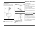
Thermo 90 / Thermo 90 S Vehicles with Diesel Engines Vehicles with Petrol Engines Plastic tank Fuel must be drawn from the fuel tank or a separate tank (see Figs. 5, 6 and 7). When fuel is supplied from a separate tank, any pressure-related influence can be excluded. In the case of carburettor or injection engines equipped with return lines, the heater’s fuel system is to be integrated in the return line.
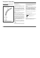
Thermo 90 / Thermo 90 S Fuel Lines correct Only steel, copper and plastic pipes made of plasticized, light-resistant and temperature-stabilized PA 11 or PA 12 (e.g. Mecanyl RWTL) in accordance with DIN 73378 may be used. NOTE: Do not cut Mecanyl lines using a side cutter. to engine from tank to metering pump Fig. 8: Webasto Fuel Pickup If the heater is installed in vehicles equipped with injection systems it is therefore to be determined whether the fuel pump is mounted inside or outside the tank.
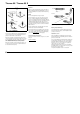
Thermo 90 / Thermo 90 S 12-volts and 24-volts - Petrol and Diesel Installation and Mounting The combustion air inlet must not be located above the exhaust gas outlet. The metering pump is to be attached by vibration-damping suspension. The installation position is restricted in accordance with Figs. 10 and 11 in order to ensure sufficient selfventilation. preferably 15°-90° Fig.
Thermo 90 / Thermo 90 S Unique to Thermo 90-TRS: For legal provisions relating Electrical Connections to the routing of the exhaust pipe refer to Technical Information E3 - 5.10 (order no. 776 623). Control Unit/Heater Connection To ensure an angle of discharge of 90° ± 10°, it is required that the pipe clamp be attached no more than 150 mm, from the exhaust pipe end The electrical connection of the heaters is to be carried out in accordance with circuit diagrams Figs. 16, 17, 18, 19 and 20.
Thermo 90 / Thermo 90 S Control Unit Thermo 90 Control Unit Thermo 90 S NOTE: Control units for the 12-volt variant are provided with red labelling, those for the 24-volt variant with green labelling. In the installation position as shown in Fig. 15 the control unit conforms to IP6K4K type of enclosure. The control unit should be installed in a protected location, preferably in the driver’s cab. In the installation position as shown in Fig.
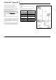
Thermo 90 / Thermo 90 S Legend for circuit diagrams: ➀ this terminal is not used for petrol-operated heaters.
Thermo 90 / Thermo 90 S Pos. A1 A2 B1 B2 B3 B4 E F1 F2 F3 H1 H2 H3 H4 H5 H6 Designation Heater Electronic control unit Flame detector Temperature sensor Temperature limiter Interior-temperature thermostat Pencil-type glow plug Fuse 20A Fuse 5A Fuse 20A Symbol for “Heating” on display LED in pos. S4 LED LED max. 20 mA Lamp min. 1.2 W Red LED (in pos. P2) K1 K2 K5 K6 M1 M2 M3 P P1 Relay (in pos. A2) Relay (in pos.
Thermo 90 / Thermo 90 S ϑ Fig.
Thermo 90 / Thermo 90 S ϑ Fig.
Thermo 90 / Thermo 90 S ϑ Fig.
Thermo 90 / Thermo 90 S ϑ Fig.
Thermo 90 / Thermo 90 S ϑ Fig.
Thermo 90 / Thermo 90 S Initial Operation After the heater has been installed, the water circuit and the fuel supply system must be thoroughly bled. When so doing, the vehicle manufacturer’s instructions must be adhered to. During a test run of the heater, all water and fuel connections must be checked for leakage and security. Should the heater shut down during operation, troubleshooting activities must be carried out.
Thermo 90 / Thermo 90 S Malfunctions Diagnosis in the Event of a Fault Shutdown Thermo 90 S Fault Shutdown Check fuses and electrical connections. If the flame fails to materialize fuel is delivered for max. 180 seconds. After the occurrence of a malfunction, the fault is indicated on the display of the digital timer if the heater is equipped with a standard digital timer: If the flame is extinguished during operation fuel is delivered for max. 90 seconds.
Thermo 90 / Thermo 90 S Diagnosis in the Event of a Fault Shutdown of Thermo 90 Check fuses and electrical connections. If the heater is activated by the switch or the timer with 3 time settings, the different types of malfunctions are indicated by coded flashing signals via the operation indicator light during the after-run period of the heater.
Thermo 90 / Thermo 90 S Technical Data Unless tolerances are shown within the technical data table on the right, a tolerance of ± 10% applies at an ambient temperature of +20°C and at rated voltage. Electrical components: Control unit, motors for combustion air fan and circulating pump, pencil-type glow plug, switch and digital timer (presetting of operating times not possible in the case of TRS vehicles) are designed either for 12-volt or 24-volt operation.
Thermo 90 / Thermo 90 S Variants Thermo 90 Variants Thermo 90 S Thermo 90 Petrol-Type (Type BW 80) Water heater for “petrol” fuel Thermo 90 S Petrol-Type (Typ Thermo 90 S B) Water heater for “petrol” fuel Thermo 90 Diesel-Type (Type DW 80) Water heater for “Diesel” fuel Thermo 90 S Diesel-Type (Typ Thermo 90 S D) Water heater for “Diesel” fuel Thermo 90-TRS (Type DW 80) Water heater Thermo 90 with TRS configuration specially designed for use in vehicles carrying hazardous materials Thermo 90-TRS (Typ
Thermo 90 / Thermo 90 S 22
Template for heater mounting bracket Scale 1:1 Gabarit de perçage pour le support de l’appareil de chauffage Echelle 1:1
Thermo 90 / Thermo 90 S 24
Subject to change Webasto Thermosysteme GmbH 82131 Stockdorf . Kraillinger Str. 5 . Phone (089) 85794-0 Fax (089) 8 57 94-448 .