Webasto BlueCool Premium Thermo 90 ST - Chiller Installation Manual CAUTION – Improper installation or repair of Webasto heating and cooling systems can cause fire or the leakage of deadly carbon monoxide leading to serious injury or death. – Installation and repair of Webasto heating and cooling systems requires special Webasto training, technical information, special tools and special equipment.
Table of Contents Contents 3 Page Foreword 4 General . . . . . . . . . . . . . . . . . . . . . . . . . . . . . . . . . . . . . . . . . . . . . . . . . . . . . . . . . . . . . . . . 4 Scope and Purpose . . . . . . . . . . . . . . . . . . . . . . . . . . . . . . . . . . . . . . . . . . . . . . . . . . . . . . . 4 Safety and Important Information . . . . . . . . . . . . . . . . . . . . . . . . . . . . . . . . . . . . . . . . . . . . 5 Symbol Identification . . . . . . . . . . . . . . . . . . . . . . . . . .
Foreword 1. Foreword General Webasto Product North America, Inc. is pleased to provide this installation manual with the Thermo 90 ST designed for the BlueCool Premium System. When used according to the guidelines stated in this manual, you can expect to provide years of trouble-free, enjoyable operation for your customer. We encourage our customers to write to us with their comments or criticisms concerning this manual or product. Thank you for your participation.
Foreword 5 2. Safety and Important Information Failure to follow the installation instructions and the notes contained therein will lead to all liability being refused by Webasto Product. The same applies if repairs are carried out incorrectly or with the use of parts other than genuine spare parts. All Webasto BlueCool (WBC) products are 110 or 220 volt components that are only allowed to be installed, connected and maintained by trained and duly certified personnel.
Foreword Symbol Identification The purpose of safety symbols is to attract your attention to possible hazardous conditions. This manual uses a series of symbols and signal words which are intended to convey the level of importance of the safety messages. The progression of symbols is described below. Remember that safety messages by themselves do not eliminate danger and are not a substitute for proper accident prevention measures.
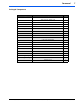
Foreword 7 Packaged Components Category Description Qty. Intake and Exhaust TUBE FLEX SS 38MM X 2M 1 TUBE FLEX PAK 30MM X 2M 1 CLAMP EXHAUST 1 1/2" 4 CLAMP HOSE AIR INTAKE 2 THRU HULL EXHAUST 1 FUEL LINE METAL (3/16"DIA) 25 FEET 1 COMPRESSION FITTING 3/16" COUPLING UNION 1 STANDPIPE W/COMPRESSION FITTING 1 COUPLER FUEL LINE STRAIGHT 1 CLAMP HOSE 9.5-10.
Installation 1. Installation General Information IMPORTANT • The Thermo 90 ST must be installed outside the passenger cabin. • The following temperature ranges apply to some components: • ABS pipe system (G. Fischer) and fittings from -40°F - 140°F (-40°C to +60°C). Use a pipe system designed for temperatures up to 248°F (120 °C), e.g. Hep2O made by Hepworth.
Installation 9 Installation Site / Installation Position The heater must be installed in as low a position as possible to allow the heater and circulating pump to be bled automatically. This is particularly important as the circulating pump is not self-priming. Fig. 2 Correct installation positions for the Thermo 90 ST Mounting the Heater The heater must be secured with at least three M8 screws. The screws must be tightened with a torque value of 13 lb-ft. (18 Nm).
Installation Hose Connections to Chiller Unit The Thermo 90 ST is intragrated into the Chiller unit water circuit via a electrically actuated 3-way valve assembly. Fig. 3 BlueCool Premium System with a Thermo 90 ST Components: 1. Stop valve at ship’s side inlet 2. Sea water filter 3. Webasto Blue Cool Premium Unit 110 / 220 volts 5. 3-way valve 6. Intermediate storage tank (optional) 7. Water heater – Thermo 90 ST 126°F (52 °C) 8. Webasto BlueCool Air Handler 110 / 220 volts 10.
Installation 11 Electrically actuated 3-way valve: Electrically actuated 3-way valves of the relevant sizes are used in chiller systems with up to 36,000 BTU. The selection is made according to the diameter of the pipe used. • 3-way valve 5/8" incl. fitting • 3-way valve 3/4" incl. fitting • 3-way valve 1" incl. fitting The hoses must be installed without kinks and (to ensure perfect bleeding) rising if possible. Hose connections must be supported by hose clips to prevent them slipping.
Installation Fuel Supply The fuel can be used from the vehicle fuel tank or from a separate fuel tank. The values for the maximum pressure at the fuel extraction point are shown in the table below. A sign must be affixed to the fuel filler neck warning that the heater must be switched off before refuelling. Permissible fuel inflow height H At max. pressure (PSI) in fuel line 0.00’ (0.00m) 2.9 PSI 3.28’ (1.00m) 0.16 PSI 6.56’ (2.00m) 0.44 PSI Maximum fuel intake height S (Ft.) At max.
Installation 13 Since the lines cannot be routed with a constant rising gradient, the internal diameter must not exceed a certain size. Air or gas bubbles will accumulate in lines with an internal diameter of more than 4 mm and will cause malfunctions if the lines sag or are routed downwards. The lines should not be routed downwards from the metering pump to the heater. Unsupported fuel lines must be secured to prevent them sagging.
Installation Combustion Air Supply WARNING Asphyxiation risk! The combustion air required for the heater may only be drawn in from the outside or from spaces that are not occupied by persons e.g. ventilated foredeck box or ventilated *engine compartment (Diesel only). The combustion air intake line (internal diameter at least 1 1/8” (30 mm) may be 1 1/2” (0.5 m) to 16 1/2” (5 m) long with several bends totalling 360°. The minimum bending radius is 1 3/4” (45 mm).
Installation 15 Heater Exhaust Route the flexible exhaust in such a way that the heat cannot affect adjacent heat sensitive materials, plastic piping, electric cables and sails etc. Make sure to use the glass / silicon protective insulating sleeve supplied in the kit to ensure surrounding objects are protected. If additional protection is required, it is recommended to over-sleeve with an additional layer of insulation (available from your local Webasto marine dealer).
Installation WARNING Avoid asphyxiation! If the exhaust pipe is routed through the inside of the vessel, exhaust gas tube must be as leakproof as possible: • use only Webasto approved exhaust clamps and firmly tighten clamps. • an approved exhaust sealant can be used on the inside of the exhaust tube at all connection points • use condensation water drain • if desired, use an optional gas tight exhaust muffler to reduce interior noise CAUTION • DO NOT fit the skin fitting below the water line.
Installation 17 Electrical System General Information Electrical connections are to be carried out in accordance with the circuit diagrams contained in this installation manual. When installing the electrical system make sure that the components are installed in protected, dry areas to prevent corrosion. If vessel only has one battery, we recommend a second battery be installed for the operation of the heater. To avoid having to charge the battery too often, its capacity should not be too small.
Installation TECC Program 412 and Higher with Thermo 90 ST and Electrical 3-Way Valve Because an external water heater (Thermo 90 ST) is being installed with a BlueCool Chiller Unit, the TECC Card must be reprogrammed for proper operation. This step must be completed in order for proper operation of the Thermo 90 ST. DEEP PROGRAMMING MODE: Numbering below in ** represent reference numbers in Fig 14. 14 Setting Code 2: 1. Programming Code 2: With unit on, lower temperature set-point to 59° F (15° C).
Installation 19 Connections on the TECC Card: R1 - Connection C1 R1 - Connection R1 R1 - Connection T1 R1 - Connection C2 R1 - Connection R2 R1 - Connection T2 Fig. 15 Chiller Unit TECC Card www.webasto.us Webasto Product N.A., Inc. www.techwebasto.
Installation Information about Air Guidance Inlets and outlets: In principle, the air guidance in the ship is designed for air conditioning operation. This means the air is extracted at floor level and blown out at ceiling level. By nature, cool air subsides so this arrangement provides a natural circulation of air. In heating mode, this circulation is weaker and, theoretically, the air is only circulated by the blower.
Circuit Diagrams 21 Circuit Diagrams Circuit diagram legend for the Thermo 90 ST 1. Temperature coding (temperature at water outlet): Refer to following circuit diagram legend for further information. 2. Vessel Fuse 3. Vessel Blower Switch Cable cross-sections < 7.5 m Item A1 A2 B1 B2 B3 B4 E F1 F2 F3 H1 Designation Heater Control module Flame sensor Temperature sensor Temperature limiter/ Overheating guard Room thermostat Glow plug Fuse 20 A Fuse 5 A Fuse 20 A “Heating” symbol in the display 7.
Circuit Diagrams Fig. 17 System Circuit for Thermo 90 ST, 12 / 24V Fig. 18 TECC Card from Chiller Unit www.webasto.us Webasto Product N.A., Inc. www.techwebasto.
Initial Start-up 23 1. Initial Start-up General After you have installed the heater, bleed the water system and the fuel supply system carefully. Conduct a trial of the heater to check all the water and fuel connections for leaks and to ensure that they are secure. If the heater suffers a fault during operation, the fault must be located and remedied.
Technical Data 2. Technical Data Except where limit values are specified, the technical data below refers to the usual heater tolerances of ± 10% at an ambient temperature of 68°F (20 °C) and at nominal voltage. Electrical components: The control module, motors for combustion air blower and circulating pump, glow plug, and switch are designed for either 12 V or 24 V. The temperature limiter, temperature sensor and flame sensor are identical on 12 V and 24 V heaters.
Troubleshooting 25 3. Troubleshooting Fault lock-out • Fuel is supplied for max. 240 seconds if the flame does not start to burn. • Fuel is supplied for max. 240 seconds if the flame goes out during operation. • The fuel supply is shut off if the system overheats (temperature limiter is tripped). If the system overheats the button on the temperature limiter must be reset. Once the cause of the fault has been eliminated, the fault lock-out is cancelled by switching the heater off and on again.
Notes www.webasto.us Webasto Product N.A., Inc. www.techwebasto.
Notes www.webasto.us Webasto Product N.A., Inc. www.techwebasto.
Webasto Product N.A., Inc. 15083 North Road Fenton, MI 48430 Technical Assistance Hotline USA: (800) 860-7866 Canada: (800) 667-8900 Org. 05/2005 Rev. N/A P/N: 5000988A www.webasto.us www.techwebasto.