
Installation manual


Installation
www.webasto.us Webasto Product N.A., Inc. www.techwebasto.com
17
Electrical System
General Information
Electrical connections are to be carried out in accordance with the circuit diagrams contained in this installation manual.
When installing the electrical system make sure that the components are installed in protected, dry areas to prevent
corrosion.
If vessel only has one battery, we recommend a second battery be installed for the operation of the heater. To avoid having
to charge the battery too often, its capacity should not be too small.
If you have highly sensitive electronic components on board, a special electrical interference suppression may become
necessary. In this case, please consult a competent specialist workshop.
When actuating the battery disconnect switch (if equipped), wait until the cool down cycle of the heater has been
completed.
Control Module / Heater Connection
The electrical connection of the heaters is undertaken in accordance with the circuit diagrams in Figures 13, 15, 17, and 18.
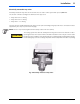
Thermo 90 ST Control Module
The control module offers protection type 6K9K if it is installed in the position shown in Fig. 13.
24 V
XXXXXXX_.XXXXX
Fig. 13 Thermo 90 ST Control Module, Arbitrary Installation Position