Coolant Heater Thermo Pro 90 D (Diesel) 12 / 24 Volt Installation Manual – Improper installation or repair of Webasto heating and cooling systems can cause fire or the leakage of deadly carbon monoxide leading to serious injury or death. – Installation and repair of Webasto heating and cooling systems requires special Webasto training, technical information, special tools and special equipment.
Thermo Pro 90 Table of Contents Contents Page 1. Safety and General Information 1.1 1.2 5 Warning Symbols in this Installation Manual . . . . . . . . . . . . . . . . . . . . . . . . . . . . . . . . . . . . . . . . . . . . . . . . . . . . . . . 5 General Information . . . . . . . . . . . . . . . . . . . . . . . . . . . . . . . . . . . . . . . . . . . . . . . . . . . . . . . . . . . . . . . . . . . . . . . . . 5 2. Regulation for Installation in the Vehicle 6 2.1 2.2 2.3 2.4 2.5 2.6 Scope . . . . . .
Table of Contents Thermo Pro 90 14.2 Heater Interlock . . . . . . . . . . . . . . . . . . . . . . . . . . . . . . . . . . . . . . . . . . . . . . . . . . . . . . . . . . . . . . . . . . . . . . . . . . . .35 14.2.1 Interlock Reset Procedure . . . . . . . . . . . . . . . . . . . . . . . . . . . . . . . . . . . . . . . . . . . . . . . . . . . . . . . . . . . . . . .35 14.3 Diagnostic after a Fault Lock-out for the Thermo Pro 90 . . . . . . . . . . . . . . . . . . . . . . . . . . . . . . . . . . . . . . . .
Thermo Pro 90 Safety and General Information 1. Safety and General Information 1.1 Warning Symbols in this Installation Manual The purpose of safety symbols is to attract your attention to possible hazardous conditions. This manual uses a series of symbols and signal words which are intended to convey the level of importance of the safety messages. The progression of symbols is described below.
Regulation for Installation in the Vehicle 2. Regulation for Installation in the Vehicle 2.3 2.1.1 2.1.2 2.2 Scope Subject to the provisions of paragraph 2.1.2, internal combustion heaters must be installed in accordance with the requirements contained in this Annex. The fuel filler neck must not be located in the passenger compartment and must have a tightly fitting cap to prevent any fuel leaks. 2.3.
Thermo Pro 90 2.7.2 Regulation for Installation in the Vehicle The water outlet hose must be protected so that it cannot be obstructed by other objects or the flow of water through the hoses. IMPORTANT! Failure to follow the installation instructions and the notes contained therein will lead to all liability being refused by Webasto. The same applies if repairs are carried out incorrectly or with the use of parts other than genuine Webasto service parts.
Purpose / Version Thermo Pro 90 3. Purpose / Version 3.1 Purpose of the Coolant Heater The Webasto Thermo Pro 90 coolant heaters are used in connection with the vehicle’s own heating system – – – – to heat the cab, to defrost vehicle windows and to preheat water-cooled engines, to heat boats and motor-homes (recreational vehicles) The water heater operates independently of the engine and is connected to the cooling system, the fuel system and the electrical system of the vehicle.
Thermo Pro 90 Installation 4. Installation IMPORTANT! exhaust temperature sensor and the loose routing of the exhaust temperature sensor cable to the control unit must be ensured during installation. The water heater must be installed outside the passenger cabin. 4.3 The requirements of the latest version of “Hazmat” must also be observed for the installation of the heater into vehicles used to transport hazardous substances. 4.
Installation Location Examples Thermo Pro 90 5. Installation Location Examples Figure 1: Installation locations Webasto Thermo & Comfort N.A., Inc. 10 www.techwebasto.
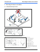
Thermo Pro 90 Mounting the Heater to the Vehicle 6. Mounting the Heater to the Vehicle 6.1 Allowable Mounting Positions 3 1 2 Coolant Direction Fuel Connection Figure 2: Allowable enclosure kit mounting positions, 1 and 2 only. Position 3 is not permissible. Figure 3: Permitted installation positions for the Thermo Pro 90 heaters 1 - Fuel inlet 2 - Heat exchanger outlet 3 - Heat exchanger inlet 4 - Exhaust outlet 5 - Combustion air inlet A - Height 232mm (9.13”) B - Width 140mm (5.
Mounting the Heater to the Vehicle Thermo Pro 90 Do not drill holes through top or bottom of vehicle frame flanges! CAUTION Do not weld vehicle frame or flanges! mm ) 80 /32” 5 (3mm ) 70 3/4” (2- Figure 5: Drill frame within the shaded area only! 310mm (12-13/64”) 80mm (3-5/32”) 70mm (2-3/4”) 150mm (5-29/32”) 23mm (29/32”) 50mm (1 31/32”) Figure 6: Mounting heater enclosure via back wall (Vertical or horizontal mounting) Webasto Thermo & Comfort N.A., Inc. 12 www.techwebasto.
Thermo Pro 90 Mounting the Heater to the Vehicle 150mm 150mm 484mm 363mm 158mm 500mm Figure 7: Optional perpendicular mounting with bracket kit P/N 905838 www.webasto.us 13 Webasto Thermo & Comfort N.A., Inc.
Connection to the Vehicle Cooling System Thermo Pro 90 7. Connection to the Vehicle Cooling System 7.1 General Information The heater is connected to the vehicle cooling system as shown in Figures 9 through 14, depending on the type of heating system the vehicle is equipped with. The system must contain at least 6 litres (1.6 US Gal.) of coolant. The system must be filled with an antifreeze and water mixture as recommended by the vehicle manufacturer.
Thermo Pro 90 Connection to the Vehicle Cooling System The cooling system must be bled carefully before using the heater for the first time or after replacing the coolant. Proper venting of trapped air can be identified by the circulating pump operating almost silently. Poor bleeding may cause the resetting temperature limiter to trip while the heater is in operation. 7.
Connection to the Vehicle Cooling System 2 Thermo Pro 90 2 7 1 1. 2. 3. 4. 5. 6. 7. Coolant supply connection Vehicle heat exchangers Coolant pump Thermo Pro 90 heater Coolant return connection Engine coolant pump Thermostat 6 4 5 3 Figure 11: System configured in series with rear heat exchanger in a “dual” circuit heating system. 2 2 7 1 1. 2. 3. 4. 5. 6. 7.
Thermo Pro 90 11 Connection to the Vehicle Cooling System 2 2 8 7 9 1 9 6 4 1. 2. 3. 4. 5. 6. 7. 8. 9. 10. 11. Coolant supply connection Vehicle heat exchangers Coolant pump Thermo Pro 90 heater Coolant return connection Engine coolant pump Thermostat Automated control valve Wye connectors N/A Auxiliary heat exchanger 5 3 Figure 14: System configured with an additional auxiliary heat exchanger connected in “series / parallel” with rear heat exchanger circuit. www.webasto.
Fuel Supply Thermo Pro 90 8. Fuel Supply 8.1 General Information The values for the maximum pressure at the fuel extraction point are shown in the table below and in Figure 16. Intake Side Pressure Side D1- Inside diameter of fuel line = 2 mm. D2: Inside diameter of fuel line = 2 mm.
Thermo Pro 90 8.2 Fuel Supply Fuel Standpipe Installation To install the standpipe: This separate fuel pickup precludes any effect of pressure. 1. bore a 25mm (1”) hole through top of fuel tank (item G, Figure 17). 2. remove sharp burrs and smooth edges with emery cloth. 3. determine length of standpipe when installed. End should sit at least 25mm (1”) above tank bottom. Cut off excess standpipe at a 45 degree angle. Remove burrs. 4. loosely assemble items C, D, E, and F (Figure 17). 5.
Fuel Supply Thermo Pro 90 7. bring standpipe up to horizontal and insert opposite shoulder under the tank hole. See Figure 19. 8. center standpipe in tank hole. See Figure 20. Figure 20: Standpipe installation - illustration 3 9. pull up on standpipe and tighten in place with the clamping nut (item A in Figure 21).
Thermo Pro 90 8.3 Fuel Supply Fuel Lines Only steel and plastic lines made of plasticized, light and temperature-stabilized may be used for the fuel lines. Since the lines normally cannot be routed with a constant rising gradient, the internal diameter must not be allowed to exceed a certain size. Air or gas bubbles will accumulate in lines with an internal diameter of more than 4 mm (5/32 in.) and these will cause malfunctions whilst the heater is operating if the lines sag or are routed downwards.
Fuel Supply 8.4.2 Thermo Pro 90 Attachment The metering pump must be secured with a vibrationdamping mounting. Its installation position is limited as shown in Figure 24 in order to ensure effective automatic bleeding. As a result of the risk of corrosion, only genuine Webasto parts may be used for the plug connections between the metering pump and the metering pump wiring harness. 8.5 Fuel Filter Only a Webasto filter is allowed to be used if the fuel is expected to be contaminated.
Thermo Pro 90 Combustion Air Supply 9. Combustion Air Supply Under no circumstances may the combustion air be taken from areas occupied by people. The combustion air intake opening must not point in the direction of travel. It must be located in that it cannot become clogged with dirt or snow and cannot suck in splashing water. IMPORTANT! The combustion air must be extracted using a combustion air tube from a position that is as cool as possible and protected from splashing water.
Exhaust System Thermo Pro 90 10. Exhaust System The exhaust pipe (internal diameter 38 mm) can be installed with a length of 0.5 m to 5 m (1.6 ft to 16 ft) and several bends totalling a maximum of 360° altogether. The minimum bending radius is 85 mm (3.35 inches). The exhaust muffler is required and must be installed near the heater. The opening of the exhaust pipe must not point towards the front of the vehicle (see Figure 27).
Thermo Pro 90 Exhaust System The exhaust pipe must be securely attached no further than 150 mm (6 in.) from the end of the exhaust pipe to ensure that the angle of 90° ± 10° vertical-down is maintained.
Electrical Connections Thermo Pro 90 11. Electrical Connections 11.1 Power / Control Harness Connections Ideally, the heater power supply should be directly from the vehicle’s batteries or main buss-bar. The heater control unit is equipped with low voltage protection. It is imperative that the vehicle batteries be kept in good condition for optimal heater operation. For sleeper and engine heating applications, Webasto recommends a four battery system for best results.
Thermo Pro 90 Electrical Connections 11.2 Connecting the Controls The heater can be switched on and off using the following Webasto controls: • Switch, see circuit diagrams in Figures 29 and 33. • Timer, see circuit diagrams in Figures 30 and 34. 11.2.1 Toggle Switch 1 2 3 4 Heater Control Harness Connection Using a 24 Volt Switch 1. 2. 3. 4. White (Ground) Red (Power) Black (On signal) Green (Operation indication) Figure 29: Toggle switch 11.2.
Electrical Connections Thermo Pro 90 The Control Panel should be installed in a suitable location on a flat surface if possible in a visible area. – Connect control panel to existing connectors on heater-unit wiring harness (see “Connections Diagrams Section”) – Use the drilling dimensions (fig. 32) to lightly mark the two mounting holes. – (Optional Step) To route wire harness through the mounting surface, drill a 17mm (11/16”) hole.
Thermo Pro 90 Electrical Connections 11.3 Vehicle Fan The vehicle's own heater fan can be controlled using a relay, see circuit diagram Figs. 33 or 34 (connecter X8 contact 2 Violet or contact D of X13. 11.4 Setting Control Temperatures of Thermo Pro 90 When the ignition signal is connected to the control unit connector X8, contact 7, different control thresholds are effective.
Circuit Diagrams Thermo Pro 90 12. Circuit Diagrams Cable Cross Sections Webasto Thermo & Comfort N.A., Inc. Cable Colors Legend 30 www.techwebasto.
Thermo Pro 90 Circuit Diagrams 12.
Circuit Diagrams Thermo Pro 90 Figure 33: Thermo Pro 90 with ON/OFF Switch - Connection Diagram Webasto Thermo & Comfort N.A., Inc. 32 www.techwebasto.
Thermo Pro 90 Circuit Diagrams Figure 34: Thermo Pro 90 with 7-day SmarTemp Control fx Timer - Connection Diagram www.webasto.us 33 Webasto Thermo & Comfort N.A., Inc.
Initial Start-up Thermo Pro 90 13. Initial Start-up IMPORTANT! Refer to the safety instructions in the operating and maintenance instructions. The operating and maintenance instructions must be read thoroughly before starting the heater. NOTE: As a result of the low fuel consumption the heater may require several start attempts to fill the fuel line and prime the system.
Thermo Pro 90 Troubleshooting 14. Troubleshooting 14.1 General Information The control unit continuously monitors the heater operation. The control unit identifies errors on individual heater components and faults during operation. Should the control unit experience component errors and operational faults, the heater will be shut down. 14.2 Heater Interlock Fuel is supplied for a max. of 240 seconds if the flame does not start. Fuel is supplied for a max.
Troubleshooting Thermo Pro 90 5x N/A 6x Coolant temperature sensor interrupt or temperature sensor short-circuit 7x Metering pump interrupt or metering pump short-circuit 8x Blower motor interrupt or blower motor short-circuit or blower motor incorrect speed 9x Glow plug interrupt or igniter short-circuit 10x Overheating 11x Circulating pump interrupt or circulating pump short-circuit 12x Battery main switch short circuit 13x Output vehicle fan short circuit 14x Overheating protection defective
Thermo Pro 90 Technical Data 15. Technical Data Except where limit values are specified, the technical data refer to the usual heater tolerances of ±10% at an ambient temperature of +20 °C (68 °F) and at the nominal voltage and conditions. 15.1 Electrical Components: The control module, motors for combustion air blower and circulating pump, ceramic glow pin, metering pump, switch and timer are available in 12 and 24 volt versions.
Thermo Pro 90 Notes 15.3 Thermo Pro 90 Dimensions 1 Combustion air intake 2 Exhaust outlet 3 Fuel inlet pipe 4 Coolant inlet 5 Coolant outlet L 355mm (14”) L* 381mm (15”) H 232mm (9.13”) B 140mm (5.5”) Figure 35: Dimensions of the Thermo Pro 90 Heater / Enclosure Box www.webasto.us 38 Webasto Thermo & Comfort N.A., Inc.
Thermo Pro 90 Technical Data NOTES www.webasto.us 39 Webasto Thermo & Comfort N.A., Inc.
Webasto Thermo & Comfort N.A., Inc. 15083 North Road Fenton, MI 48430 Technical Assistance Hotline USA: (800) 860-7866 Canada: (800) 667-8900 Org. 5/2014 Rev. 12/2014 P/N 5010926A www.techwebasto.