
Installation manual


www.webasto.us 27 Webasto Thermo & Comfort N.A., Inc.
Thermo Pro 90 Electrical Connections
11.2 Connecting the Controls
The heater can be switched on and off using the following Webasto controls:
• Switch, see circuit diagrams in Figures 29 and 33.
• Timer, see circuit diagrams in Figures 30 and 34.
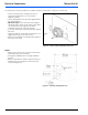
11.2.1 Toggle Switch
Figure 29: Toggle switch
11.2.2 Control Element (SmarTemp) Timer Connection
Figure 30: 7-Day, 4 Program SmarTemp Control fx Timer
All the cables and wires that are not required must be insulated against accidental
shorting or grounding.
1
2
3
4
Heater Control Harness Connection
Using a 24 Volt Switch
1. White (Ground)
2. Red (Power)
3. Black (On signal)
4. Green (Operation indication)
Heater Control Harness Connection
Using SmarTemp Control fx
1. Red (Power)
2. Brown (Ground)
3. Black or Grey (ON/OFF Signal)
4. Green (Diagnostic Blink Code)
CAUTION