
Installation manual


Webasto Thermo & Comfort N.A., Inc. 28 www.techwebasto.com
Electrical Connections Thermo Pro 90
The Control Panel should be installed in a suitable location on a flat surface if possible in a visible area.
– Connect control panel to existing connectors on
heater-unit wiring harness (see “Connections
Diagrams Section”)
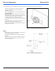
– Use the drilling dimensions (fig. 32) to lightly mark the
two mounting holes.
– (Optional Step) To route wire harness through the
mounting surface, drill a 17mm (11/16”) hole. Make
sure to push harness through the hole before
installing terminals into connector housing)
– Secure the SmarTemp Control using the two supplied
#4 screws.
– Apply the supplied “Heater Off” warning sticker in a
highly visible location to the drivers area.
– Observe the installation / operating manual supplied
for proper menu setup.
NOTES:
– Always make sure there are no obstacles behind the
mounting location prior to drilling.
– Ensure good readability when selecting installation
location.
– Observe information on adhesive labels and colored
markings when connecting the control element to
vehicles wiring harness.
Figure 31. Control element (SmarTemp Control fx)
Figure 32. SmarTemp drilling dimensions