
Installation manual


www.webasto.us 15 Webasto Product N.A., Inc.
Thermo 90 S / Thermo 90 ST Connection to the Vehicle Cooling System
The cooling system must be bled carefully before using the heater for the first time or after replacing the coolant.
Proper venting of trapped air can be identified by the circulating pump operating almost silently. Poor bleeding may
cause the resetting temperature limiter to trip while the heater is in operation.
7.2 Various Plumbing Configurations
Select the appropriate plumbing configuration according to the customers requirements and the vehicle system type.
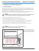
Figure 10 illustrates an engine preheat / boost heat configuration.
Figures 11 through 14 illustrate configurations for bunk heat and engine preheat / boost heat.
Figure 15 illustrates a system for vehicles with continuous fan operation or high amperage heat exchanger fan designs.
In this case, the addition of a low amperage draw, auxiliary heat exchanger system is recommended. Webasto offers a
complete kit under part number 905670 for this application.
Figure 10: System configured for engine pre-heating and boost heating.
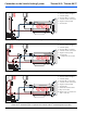
Figure 11: System configured in a “series” fashion with both heat exchangers.
1
2
3
4
5
6
7
1. Coolant supply connection
2. Vehicle heat exchanger
3. Coolant pump
4. Thermo 90 S / ST heater
5. Coolant return connection
6. Engine coolant pump
7. Thermostat
1
22
3
4
5
6
7
1. Coolant supply connection
2. Vehicle heat exchangers
3. Coolant pump
4. Thermo 90 S / ST heater
5. Coolant return connection
6. Engine coolant pump
7. Thermostat