
Installation manual


Webasto Product N.A., Inc. 18 www.techwebasto.com
Fuel Supply Thermo 90 S / Thermo 90 ST
8. Fuel Supply
8.1 General Information
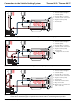
The values for the maximum pressure at the fuel
extraction point are shown in the table below and in
Figure 17.
The fuel is taken from the vehicle fuel tank or from a
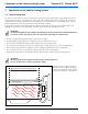
separate fuel tank. The exploded view in Figure 16
Illustrates the progression of fuel system components.
A sign must be affixed to the fuel tank’s filler neck
warning that the heater must be switched off before
refuelling.
Figure 16: Fuel system components
Figure 17: Fuel system parameters
Permissible fuel inflow
height H
At maximum pressure
in fuel line
0.00 m (0.00 in.) 0.2 bar (2.9 PSI)
1.00 m (39.4 in.) 0.11 bar (1.6 PSI)
2.00 m (78.7 in.) 0.03 bar (0.44 PSI)
Maximum fuel intake
height S
At maximum negative
pressure in the fuel tank
0.00 m (0.00 in.) -0.10 bar (-1.45 PSI)
0.50 m (19.7 in.) -0.06 bar (-0.87 PSI)
1.00 m (39.4 in.) -0.02 bar (-0.29 PSI)
l
1
+ 1
2
≤ 10 m
l
1
≤ 1.2 m
1
2
≤ 8.8 m
0
°
A
B
C
D
E
F
G
A. Fuel standpipe
B. Connector hose
C. Fuel filter
D. Hose clamp
E. Fuel pump
F. Fuel line (Mecanyl)
G. 90° Connector hose