
Installation manual


www.webasto.us 19 Webasto Product N.A., Inc.
Thermo 90 S / Thermo 90 ST Fuel Supply
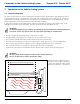
8.2 Fuel Standpipe Installation
This separate fuel pickup precludes any effect of
pressure.
Where available, a spare NPT threaded port can be
utilized for the standpipe. If a spare port is not present,
proceed with the following instructions under “To install
the standpipe”.
Figure 18: Webasto fuel standpipe
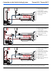
To install the standpipe:
1. bore a 25mm (1”) hole through top of fuel tank
(item G, Figure 18).
2. remove sharp burrs and smooth edges with emery
cloth.
3. determine length of standpipe when installed. End
should sit at least 25mm (1”) above tank bottom.
Cut off excess standpipe at a 45 degree angle.
Remove burrs.
4. loosely assemble items C, D, E, and F (Figure 18).
5. place sealing compound on threads of item B and
thread into item F. Tighten item B completely.
6. slide standpipe into hole at angle. Slip one shoulder
of item F, Figure 18 inside the hole as shown in
Figure 19.
Figure 19: Standpipe installation - illustration 1
A
C
B
D
E
F
25mm (1”)
Ø 25mm (1”)
Ø 25mm (1”)
Detail View
Fuel Tank
F
G
A. Fuel standpipe
B. Compression fitting
C. Hex nut
D. Metal washer
E. Rubber washer
F. Tank boss 1/4” NPT
G. 25mm (1”) hole