
Installation manual


Webasto Product N.A., Inc. 26 www.techwebasto.com
Electrical Connections Thermo 90 S / Thermo 90 ST
11. Electrical Connections
11.1 Power / Control Harness Connections
Ideally, the heater power supply should be directly from the vehicle’s batteries or main buss-bar.
The heater control unit is equipped with low voltage protection. It is imperative that the vehicle batteries be kept in
good condition for optimal heater operation.
For sleeper and engine heating applications, Webasto recommends a four battery system for best results.
A weather sealed fuse holder is to be fitted to protect the heater (supplied with the power / control
harness).
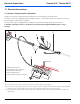
Figure 29: Power and control harness assembly
A. Route item 1 into the vehicle cab in the area where the switch or timer is to be installed.
B. Route item 4 to vehicle battery box and connect to batteries as shown in Figure 29. Brown wire to ground, red wire with fuse
holder to positive. Ensure battery connections are clean and protected with an anti-corrosive compound.
C. Item 3 (main connector) should be left unconnected until all electrical components are installed and heater is ready for the
initial start-up.
1
2
3
4
5
Vehicle System Power
Frame Ground
Main Fuse
+
+
+
+
–
–
–
–
To Heater Control Unit
1. Switch / Timer Harness
2. Heater Harness (Pre-installed)
3. Main Harness Connector
4. Power Supply Harness
5. Blower Interface Connector (3-pin)