
Installation manual


www.webasto.us 27 Webasto Product N.A., Inc.
Thermo 90 S / Thermo 90 ST Electrical Connections
11.2 Connecting the Controls
The heater can be switched on and off using the following Webasto controls:
• Switch, see circuit diagrams in Figures 30, 32 and 34.
• Timer, see circuit diagrams in Figures 31, 33 and 35.
Figure 30: Toggle switch
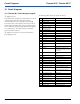
Figure 31: 7-Day, 3 Program Comfort Timer model 1531
All the cables and wires that are not required must be insulated against accidental
shorting or grounding.
1
2
3
4
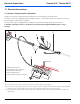
Heater Control Harness Connection
Using a 12 or 24 Volt Switch
1. White (Ground)
2. Red (Power)
3. Black (On signal)
4. Green (Operation indication)
2
8
11
101
12
7
4
H3
P2
H1
H6
6
3
4
1
2
7
5
8
X1
X8
X13
X11
X10
X12
X15
X9
X3
X4/X5/X6/X7
3
6
9
12
1 2
1 2
1
2
A
B
C
3
4
6
7
8
5
1
2
EB2 B3
M1
M2
B1
1
3
5
7
9
11
3
4
1
2
1
2
1
2
1
2
X2
F3
F2
F1
Red
White
Red
Red
Red
X8
1
2
4
3
5
6
7
8
9
10
11
12
1
21
2
122224 1
11
12
1
2
X10
Yellow/Red
Yellow
Brown
Brown
Brown
Brown
Black
Blue
Black
Blue
White/Blue
Violet/Blue
Gray
Orange
Orange
Green
Blue
Brown
VioletViolet
Violet
Gray
Gray
Green
Green
Red
Yellow
A
B
CDE F
B
D
C
Brown
Brown
Brown
RedRed
Red
BT
F5
A
E
F
G
H
J
Brown
Gray
Red/Black
Black
Black
WhiteWhite
Violet
White
Violet
Brown
Black
Green
Red
Red
Red
Red
Brown
Brown
Brown
White
White
Brown
E
M1
MM
M2
B3
B1
B2
Y1
A1
A2
A
B
C
Violet
Brown
Brown
Red
Yellow
Black
Gray
Black
Red
White
Violet
X13
X14
X9
12
X2 X4 X1 X5 X6 X7 X3
X11
X15
X12
Heater Control Harness Connection
Using 1531 Comfort Timer
1. Red (Power)
2. Not Used
3. Green (Operation indication)
4. Optional (Dash lights)
5. White (Ground)
6. Black (On signal)
Connector X2 (Violet)
For truck operation, connect to red
jumper of heater control harness.
For Coach, Transit and School Bus
operation, connect to ignition source.
CAUTION