
Operating instructions


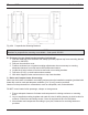


Fig. 406: Muffler Mounting Detail
B. General instructions for exhaust systems.
Modification to the exhaust system is permitted and must be done in accordance with the following
statements and instructions:
An optional exhaust pipe I.D. 1 1/2" (38 mm) can have a length up to 6.5’ (2 m) including muffler and
may have several bends (totaling 360°). It is mandatory to use the muffler. In installations where the
muffler is to be mounted other than on the enclosure box, it should be located as close to the heater
as possible.
Rigid exhaust pipe may be used, bends must be formed (smallest bending radius 3 3/8" (85 mm). Do
not weld pipe to make 90° corners. Any condensation water in the exhaust pipe must be discharged.
If necessary, drill a drain hole at the lowest point.
Route the exhaust system in such a way as to avoid touching or being directed towards any heat
sensitive materials or components (i.e., brake lines, electrical wiring, hoses).
Exhaust discharge must always be positioned straight down at point of exit plus or minus 10
degrees.
C. Basic and Compact Heater Kits.
1. Mount muffler as close to heater as possible.
2. Run exhaust tubing from heater to muffler and from muffler to an appropriate discharge area.
3. Secure all exhaust connections with clamps provided.
4. Position exhaust discharge end of tubing straight down (see figure 407) and clamp securely
in place.
One meter (39 inches) of flexible exhaust tubing is supplied with Basic and Compact heater kits.
405
Thermo 90 S 4 Installation
NOTE
Additional flexible exhaust tubing is available from your Webasto Distributor or Dealer under part
number 353 221.