
Technical data


8 Servicing Thermo 90
804
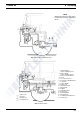
Fig. 801 Example for Heater Installation in Lorry
8.6 Visual Inspections and Installation
Regulations
8.6.1 Connection to the Vehicle's Cooling
System
In thermostat circuits only thermostats opening at < 65° C
are to be used.
The installation of the heater should be in a location as
low as possible to ensure self-venting of the heater and
ci
rculation pump. This applies in particular for the
circulation pump, which is not self-sucking.
The heater is to be connec
ted to the cooling system
according to Fig. 801. The amount of coolant in the
cooling system must be at least 6 litres.
As a rule, the coolant hoses supplied by Webasto
to
gether with the heater are to be used. Otherwise the
ho
ses must at least meet the requirements of DIN 73411.
The hoses must be routed without kinking, and for proper
venting where possible in an upwards direction.
Hose connections must be sec
ured with hose clamps to
prevent slippage.
NOTE
Hose clamps must be torqued to 1.5 Nm (clamps
pr
eviously in use) or to 5.0 Nm (new, wide clamps).
Prior to first operation of the heater or after replacement
of the coolant, bleed the cooling circuit. Heater and lines
ha
ve to be installed so that a static venting is guaranteed.
Insufficient venting during heating operation may cause
fa
ilure due to overheating.
Proper venting is indicated by a circ
ulation pump almost
noiseless in operation. Insufficient venting during heating
operation may cause release of the resettable
temperature limiter.
8.6.2 Connection to the Vehicle's Fuel System
Fuel is tapped from the fuel reservoir of the vehicle or from
a separate fuel container.
The rated pressure at the fuel tapping location is shown
in the following table.
Fig. 802 Fuel Supply
previous new
Permissible fuel feed
height H (m)
at max. permissible over-
pressure (bar) in fuel tank
0.00 0.20
1.00 0.11
2.00 0.03
Permissible fuel suction
heig
ht S (m)
at max. permissible low
pressure (bar) in fuel tank
0.00 – 0.10
0.50 – 0.06
1.00 – 0.02
max. 3 m
i ø 2 mm
i ø 2 mm
S
H
i ø 2 mm
l
1
l
1
i ø 2 mm
l
2
l
2
HG
HG
l
1
+ l
2
≤ 10.0 m
l
1
≤ 1.2 m
l
2
≤ 8.8 m