
Technical data


Thermo 90 8 Servicing
807
8.6.3.1 Installation Location
It is advantageous to mount the dosing pump in a cool
lo
cation as near as possible to the tank. The ambient
temperature must never exceed +20° C for fuel and
+40° C for Diesel operated installations at any time while
in o
peration. The maximum pressure at the tapping
location must be below 1.5 bar.
Dosing pump and fuel lines must not be installed in
loca
tions exposed to heat radiated by hot vehicle
components. A heat shield is to be provided as required.
8.6.3.2 Installation and Attachment
The dosing pump is to be attached with anti-vibration
mounts.
The installation location is limited according to
Fig. 807 to ensure sufficient self-venting capability. Due
to the danger of corrosion the plug
connection between
dosing pump and dosing pump cable loom may only use
Webasto original parts.
8.6.4 Fuel Filter
If there is the probability of contaminated fuel, only the
Webasto filter, Order No. 487 171, may be used. The
filter can be installed anywhere between the vertical and
ho
rizontal positions, but must be installed in the direction
of flow.
8.6.5 Combustion Air Supply
Combustion air must under no circumstances be
extracted from rooms with persons. The combustion air
inlet must not point towards the forward direction of
motion. It must be located so that no clogging by
contamination, impact of snow, or intake of splash water
is possible.
The combustion air intake line (inner diameter at least
30 mm) may have a length from 0.5 m to 5 m with several
be
nds of a total of 360°. Smallest bending radius is
45 mm.
The combustion air inlet must not be located above the
exh
aust outlet.
NOTE
The combustion air intake line is to be routed in a
downwards
direction. If this is not possible, a water drain
hole (4 mm Ø) must be provided at the lowest point.
If the heater is located near
the fuel tank in a common
installation compartment, combustion air must be taken
in from, and the exhaust routed to, the exterior. The
feed-throughs must be splash waterproof.
If the heater is located in a closed installation box,
a vent port of at least 6 cm
2
is required. If the temperature
in the installation box exceeds the permitted ambient
temperature of the heater (see Technical Data), the vent
port must be enlarged consulting Webasto.
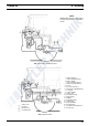
8.6.6 Exhaust Line
The exhaust line (inner diameter 38 mm) may have a
length from 0.5 m to 5 m and be routed with several bends
(a total of 360°, smallest bending radius 85 mm). The
exhaust muffler is mandatory and to be mounted near the
heater.
In order to ensure the angle of 90° ± 10°, an attachment
is required not further than 150 mm away measured from
the
exhaust pipe end.
Fig. 808 Exhaust Muffler, Direction of Flow
The exhaust pipe outlet opening must not point in the
dir
ection of motion (see Fig. 808).
The exhaust pipe outlet opening mu
st be located so as not
to allow clogging by snow or mud.
Rigid exhaust-line pipes can be mode of unalloyed or
allo
yed steel, but must have a minimum wall thickness of
1.0 mm. Flexible exhaust pipes must be made only of
alloyed steel. The exhaust pipe is secured to the air heater
with a clamp. For further requirements refer to official
regulations.
For Thermo 90 TRS only: For official regulations
concerning the exhaust pipe installation refer to Technical
Information E3 - 5.10 (Order No. 776 623).
10°
10°
Exhaust exit direction
nearly vertical 90° ± 10°