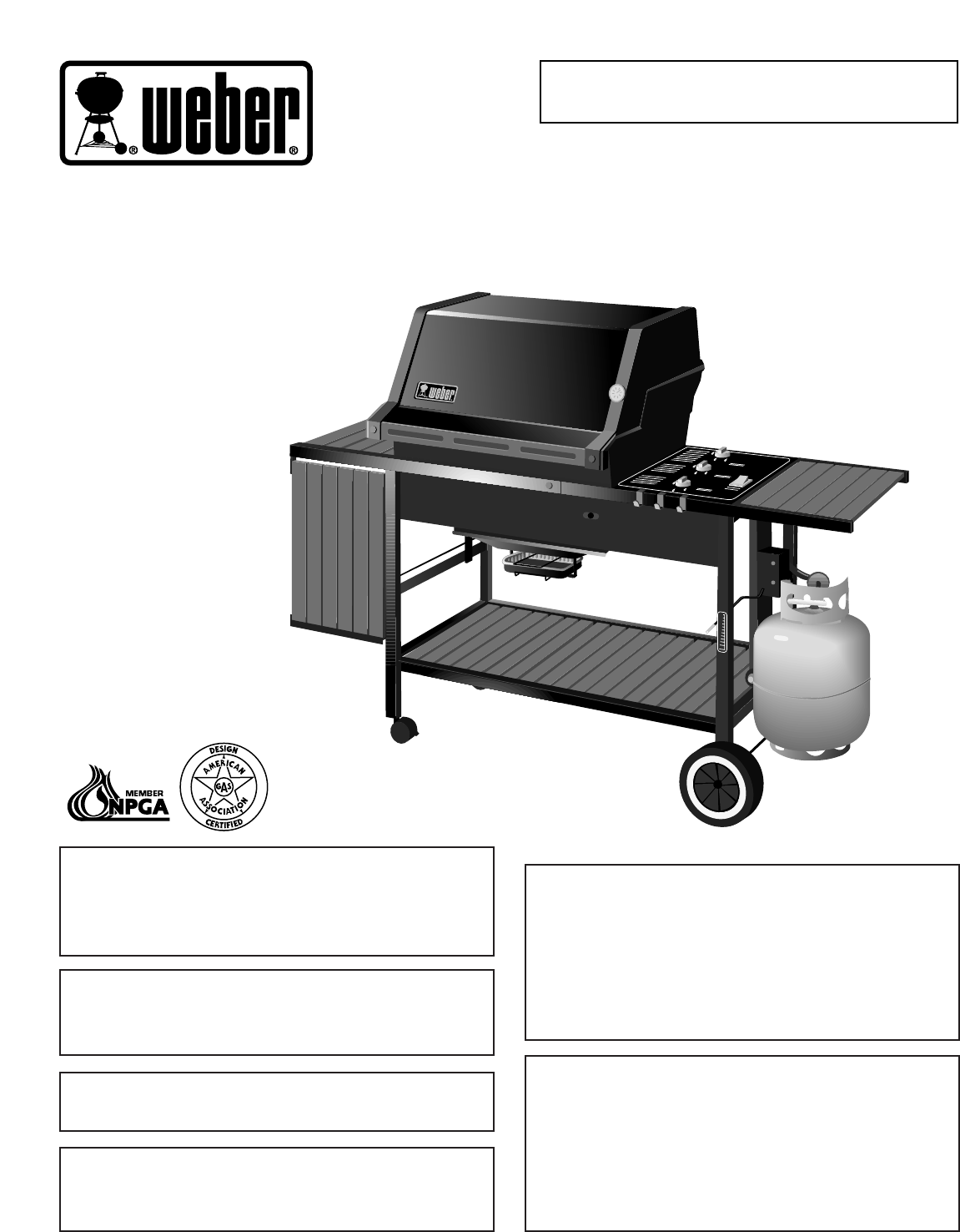
Serial Number Please use this number in registering your warranty and any correspondence with the factory. GENESIS 2000 LX Series ® LP Gas Barbecue Owner’s Manual W E B B ER ER W ® E National PROPANEGAS Association WARNING: Follow all leak check procedures carefully in this manual prior to barbecue operation. Do this even if barbecue was dealer assembled. NOTICE TO INSTALLER: These instructions must be left with the owner and the owner should keep them for future use.
DANGER Failure to follow the Dangers, Warnings and Cautions contained in this Owner’s Manual may result in serious bodily injury or death, or in a fire or an explosion causing damage to property. WARNINGS Do not store a spare or disconnected LP tank under or near this barbecue. Improper assembly may be dangerous. Please carefully follow the assembly instructions in this manual.
WARRANTY Weber-Stephen Products Co. (Weber) hereby warrants to the ORIGINAL PURCHASER of this Weber Gas Barbecue that it will be free of defects in material and workmanship from the date of purchase as follows: There are no other express warrants except as set forth herein and any applicable implied warranties of merchantability and fitness are limited in duration to the period of coverage of this express written Limited Warranty.
© 1997 Weber. Weber, , Genesis, Flavorizer and Crossover are registered U.S. trademarks; Perma-Mount, Gas Catcher, FlameCheck, Steam-N-Chips, Spider Stopper, and Warm-Up are U.S. trademarks of Weber-Stephen Products Co., 200 East Daniels Road, Palatine, IL 60067-6266. U.S.A. Printed in the U.S.A.
Contents Troubleshooting & Maintenance Annual Maintenance ........................................ 28 General Maintenance.................................. 29-31 Troubleshooting ............................................... 32 Parts Listing .............................................................. 35 WARNINGS ................................................................ 2 Warranty & Patents.................................................. 3-4 General Instructions.................................
General Instructions Storage Your Weber Gas Barbecue is a portable outdoor cooking appliance. With the Weber Gas Barbecue you can grill, barbecue, roast and bake with results that are difficult to duplicate with indoor kitchen appliances. The closed lid and Flavorizer Bars produce that "outdoor" flavor in the food. The Weber Gas Barbecue is portable so you can easily change its location in your yard or on your patio. Portability means you can take your Weber Gas Barbecue with you if you move.
Step 1 Assembly Check package contents Tools needed Regular screwdriver Cooking box (assembly) Phillips screwdriver Hammer 7/16 inch or an adjustable wrench Lid (assembly) Pliers ® ® Block of wood Supplies needed LP tank Your LP tank is shipped empty for safety. After setting the LP fuel scale you will need to fill it. (See Step "Fill LP tank.") You will need a soap and water solution to check for gas leaks. (See Step "Check for gas leaks.
Control panel Right frame Front panel Caster frame Left frame Two casters Wheel frame Two cooking grates Two frame connectors Warming rack Tank panel assembly Warm-Up Basket Five long Flavorizer Bars Thermometer Eight short Flavorizer Bars WE BE R Two wheels WE B E R Left hand slide bar assembly Assembly consists of: Left hand slide bar Two aluminum drip pans Support rod Catch pan Slide Axle 8
Fuel scale assembly Five 1/4-20 x 2 inch bolts (actual size) Six 1/4-20 x 1/2 inch bolts (actual size) Catch pan holder Two 1/4-20 wing nuts (actual size) Manifold bracket Two 10-24 x 1 3/4 machine screws (actual size) Spacer bracket Two 10-24 hex nuts (actual size) Check contents of hardware packs Eighteen 1/4 inch nylon washers (actual size) Three burner control knobs 1/4-20 keps nut Three tool holders 1/4-20 x 1 1/4 inch bolt (actual size) 1/4-20 hex nut (actual size) Five tubing plugs (two are s
Step 3 Assemble wheels Assemble frame You will need: axle, two wheel hubcaps, two wheels, wheel frame, hammer and a block of wood. You will need: left frame, right frame, two nylon washers, two 1/4-20 x 1/2 inch bolts and a 7/16 inch wrench. Place one end of the axle on the block of wood (or other protected surface). Tap on one hubcap. Note - Work on carpeted area (on grass, or on one of the boxes) to protect the finish during frame assembly. Put one wheel on the axle, WEBER side toward the hubcap.
Step 4 Step 5 Continue frame assembly Complete frame assembly You will need: frame assembly, wheel frame assembly, front panel, caster frame, four 1/4-20 x 1/2 inch bolts, four nylon washers and a 7/16 inch wrench. You will need: partial frame assembly, two frame connectors, four 1/4-20 x 2 inch bolts, four nylon washers and a 7/16 inch wrench. Place the caster frame onto the tabs of the left frame with the dimple to the inside. Figure 3.
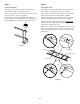
Step 7 Your Weber Gas Barbecue burner assembly has been factory assembled, pressure and flame tested. As a safety precaution we recommend you check the burner alignment: Add cooking box You will need: frame assembly, cooking box assembly, 1/4-20 x 2 inch bolt, 1/4 inch nylon washer, 1/4-20 keps nut, pliers and a 7/16 inch wrench. a) Do the valves fit into the ends of the burners? Figure 8 (a). Uncoil the hose.
Step 8 Step 9 Install manifold bracket Install tank panel assembly You will need: manifold bracket You will need: tank panel assembly, 1 1/4 inch bolt, 1/4-20 hex nut, 1/4 inch nylon washer and a 7/16 inch wrench. Hook the bracket onto the manifold at the center burner valve. Figure 9. Place your hand underneath the bracket. Lift the bracket, manifold and cooking box slightly as a unit and hook onto the frame brace. Insert the tank panel tabs into the slots in the frame brace.
Step 10 Step 11 Add fuel scale assembly Install igniter You will need: fuel scale, two 1/4-20 wing nuts and two nylon washers. Note - The igniter wires are already attached to the Gas Catcher Ignition Chamber and the igniter. This was done to factory test the ignition system. Slip the bolts on the back of the fuel scale assembly through the two small holes in the tank panel. Make sure indicator rod of fuel scale is on the left side of the wheel frame. The igniter lock nut is on the igniter.
Step 12 Step 13 Set LP fuel scale Fill LP tank You will need: LP tank (empty). Note - The LP tank manufacturer is responsible for the materials, workmanship and performance of the tank. If the tank has a defect, malfunctions, or you have a question regarding the tank, call the tank manufacturer's customer service center. The phone number is on the warning decal which is permanently attached to the tank.
Route the hose so it will not interfere with the scale indicator rod. Step 14 Check that the burner valves are off The hose and regulator are connected in the following manner: You will need: one burner control knob. Valves are shipped in the OFF position, but you should check to be sure. Put the knob on each valve. Check by pushing down and turning clockwise. If they do not turn, they are off, proceed to the next step. Figure 14. Slide back the collar of the quick disconnect on the tank valve.
Step 16 Check: Check for gas leaks a) Hose to manifold connection. Figure 18 (a). b) Regulator to tank connection. Figure 18 (b). DANGER WARNING: If there is a leak at connection (a), retighten the fitting with a wrench and recheck for leaks with soap and water solution. Do not use an open flame to check for gas leaks. Be sure there are no sparks or open flames in the area while you check for leaks.
Step 17 Step 18 Install Flavorizer Bars and Cooking Grates Install the bottom tray You will need: five long Flavorizer Bars, eight short Flavorizer Bars and two cooking grates. You will need: bottom tray, catch pan holder, catch pan and one drip pan. Set the long Flavorizer Bars side to side in the lower position, then set the short Flavorizer Bars front to back in the upper position in the cooking box. Figure 19.
Step 19 Step 20 Install the lid Install tool holders, control panel and burner control knobs You will need: lid, two hinge pins and two hair pin cotters. You will need: three tool holders, control panel, two Phillips screws/washers, a Phillips screwdriver, and three burner control knobs. Set the lid in place from the rear of the barbecue. Close and align the hinge at the rear. Insert hinge pins from the outside through the hinge. Insert hair pin cotters into the small holes in the hinge pins.
Step 21 Insert one end of the hinge rod into the hole in the frame. Figure 27 (a). Install swing table Insert the other end into the hole in the swing table end bracket. Figure 27 (b). Hold the end bracket at an angle so the lower tab is inside the frame tube. Push the bracket into the frame. Check to see that the lower tab of the bracket is hooked in the slot in the frame. Figure 27 (c).
Step 22 Position slide bar assembly on the outside of the caster frame. Put a nylon washer on each 1 3/4 inch screw, insert screws through frame and slide bar assembly and add nylon washers and hex nuts. Tighten nuts using a screwdriver and pliers. Figure 28. Complete accessory installation You will need: two work tables, two accessory trays, WarmUp Basket, warming rack, thermometer, three tubing plugs and a hammer.
OPERATING INSTRUCTIONS Lighting WARNING: The burner control knobs must be in the OFF position before turning on the LP tank valve. If they are not in the OFF position, when you turn on the LP tank valve, the excess flow control will activate, limiting the flow of gas from the LP tank. If this should occur, turn OFF the LP tank valve and burner control knobs and start over. Summary lighting instructions are on the control panel.
Manual Lighting Manual Lighting 1 DANGER Failure to open lid while igniting the barbecue, or not waiting 5 minutes to allow the gas to clear if the barbecue does not light, may result in an explosive flameup which can cause serious bodily injury or death. 3 8 4 7 1) Open the lid. Figure 2. 5 2) Check that fuel scale reads more than “E”. Note - E = empty; F = full. 6 2 Figure 2 3) Make sure all burner control knobs are turned OFF. (Push each burner control knob down and turn clockwise.
Storage and/or Nonuse continued Cooking WARNING: Do not move the Weber Gas Barbecue when operating or hot. You can adjust the FRONT, CENTER and BACK burners as desired. The control settings High (H), Medium (M), Low (L), or Off (O) are described in your Weber cookbook. The cookbook uses these notations to describe the settings of the FRONT, CENTER, and BACK burners. For example, to sear steaks you would use (HHH) (all burners at high).
Connecting the filled LP tank Refilling the LP tank WARNING: Make sure that the LP tank valve is closed. Close by turning clockwise. We recommend that you refill before the scale indicator reaches "E". DANGER Note - If you run out of fuel, check the indicator setting and/or adjust the fuel scale indicator setting with the scale setting wing nut, while the tank is empty so you do not run out again. Do not use an open flame to check for gas leaks.
c) Connect the hose to the tank. Route the hose so it does not interfere with the scale indicator rod. Slide back the collar of the quick disconnect on the tank valve. Figure 5 (a). Push the male fitting of the regulator into the quick disconnect, and maintain pressure. Slide the collar closed. Figure 5 (b). If it does not engage or lock, repeat procedure. Gas will not flow unless the quick disconnect is properly engaged.
Liquid Propane (LP) Tank(s) Safe handling tips for LP Gas ■ Liquid Propane (LP) gas is a petroleum product as are gasoline and natural gas. LP gas is a gas at regular temperatures and pressures. Under moderate pressure, inside a tank, LP gas is a liquid. As the pressure is released the liquid readily vaporizes and becomes gas. ■ LP gas has an odor similar to natural gas. You should know this odor. ■ LP gas is heavier than air. Leaking LP gas may collect in low areas that prevent dispersion.
Annual Maintenance Check: a) Hose to manifold connections. Figure 8 (a). After a period of nonuse we recommend that you perform the following maintenance procedures for your safety. b) Regulator to tank connection. Figure 8 (b). WARNING: If there is a leak at connection (a), retighten the fitting with a wrench and recheck for leaks with soap and water solution. WARNING: Check hose before each use of barbecue for nicks, cracking, abrasions or cuts.
General Maintenance Weber Spider Stopper Guards Main Burner Flame Pattern Your Weber Gas Barbecue, as well as any outdoor gas appliance, is a target for spiders and other insects. They can nest in the venturi section of the burner tubes. This blocks the normal gas flow, and can cause the gas to flow back out of the air shutter. Figure 9. This could result in a fire in and around the air shutters, under the control panel, causing serious damage to your barbecue.
d) Unlatch the Spider Stopper Guards and remove. Figure 14. g) Lift and twist the burner assembly slightly, to separate the crossover tube from the burners. Figure 17. Remove the burners from the cooking box. Crossover tube Figure 14 Figure 17 h) To reinstall burners, reverse steps c) through g). e) Remove the manifold bracket and unscrew the two wing nuts that hold the manifold to the cooking box. Pull the manifold and valve assembly out of the burners and carefully set it down. Figure 15.
i) Crossover Ignition System Operations Reinstall the Spider Stopper Guards. Slightly rotate the Spider Stopper Guards so that the seams are in line with the Venturi fins. There should be no gaps in the seams or in the fit around the burners and valves. Figure 19. If the Crossover Ignition System fails to ignite the Front burner, light the Front burner with a match. If the Front burner lights with a match, then check the Crossover Ignition System.
TROUBLESHOOTING Problem Check Cure Burners burn with a yellow or orange flame, in conjunction with the smell of gas. Inspect Weber Spider Stopper Guards for possible obstructions. (Blockage of holes.) Clean Weber Spider Stopper Guards. (See Section "Annual Maintenance".) Burners do not light. -orBurners have a small flickering flame in the HIGH position. -orBarbecue temperature only reaches 250˚ to 300˚ degrees in the HIGH position.
1 40 41 ® ® 42 2 3 4 5 6 7 43 44 45 46 47 48 8 49 9 10-11 12 13 50 51 52 53 54 55 14 15 16, 11 8 18-19, 11 56 57 67 58-62 10 20 63-64 17 21 22, 23 65 W 24 W E BE R 25 66 E BE R 26 27 28 29 30 31 32 11 33 34 34 35 36 37 38 11 39
Parts List While we give much attention to our products, unfortunately an occasional error may occur. If a part is missing, do not go back to the store. Call the Weber Customer Service Center toll free 1-800-446-1071 to receive immediate assistance. Have your owner’s manual and serial number of the barbecue available for reference. All items are single quantities unless otherwise specified. Parts can be ordered directly from Weber-Stephen Products Company by phone or mail.
A FINAL WORD OF THANKS T hank you for choosing a Weber Barbecue. Our family here at Weber has worked hard to produce the highest quality products for your satisfaction. While we give much attention to our products, an occasional error may occur. Our knowledgeable Customer Service staff is prepared to help you with any problems with parts or assembly. Call our toll free number 1-800-446-1071. For quicker service, please have your owner’s manual available for reference.