Serial Number Please use this number in registering your warranty and any correspondence with the factory. GENESIS 3500 ® Natural Gas Barbecue Owner’s Manual ® WARNING: Follow all leak check procedures carefully in this manual prior to barbecue operation. Do this even if barbecue was dealer assembled. NOTICE TO INSTALLER: These instructions must be left with the owner and the owner should keep them for future use.
DANGER Failure to follow the Dangers, Warnings and Cautions contained in this Owner’s Manual may result in serious bodily injury or death, or in a fire or an explosion causing damage to property. WARNINGS Do not store a spare or disconnected LP tank under or near this barbecue. Improper assembly may be dangerous. Please carefully follow the assembly instructions in this manual.
WARRANTY Weber-Stephen Products Co. (Weber) hereby warrants to the ORIGINAL PURCHASER of this Weber Gas Barbecue that it will be free of defects in material and workmanship from the date of purchase as follows: There are no other express warrants except as set forth herein and any applicable implied warranties of merchantability and fitness are limited in duration to the period of coverage of this express written Limited Warranty.
PATENTS AND TRADEMARKS © 1997 Weber. Weber, , Genesis, Flavorizer and Crossover are registered U.S. trademarks; Per ma-Mount, Gas Catcher, FlameCheck, Steam-N-Chips, Spider Stopper, and Warm-Up are U.S. trademarks of Weber-Stephen Products Co., 200 East Daniels Road, Palatine, IL 60067-6266. U.S.A. Genesis Gas Barbecues are covered under the following patent nos.: U.S.A. #4,677,964; 4,727,853; #4,777,927; #4,829,978; #4,860,724; #4,941,817; #4,966,125; #5,070,776; #D293,067; #D316,355; Canada: Rd 1987 Reg.
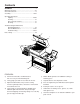
Contents WARNINGS ................................................................ 2 Warranty & Patents .................................................. 2-3 General Instructions.................................................... 6 Assembly ............................................................. 10-27 Operating Instructions Lighting........................................................ 28-30 Cooking ............................................................ 31 After a Period of Nonuse ..........
General Instructions Your Weber Gas Barbecue is a stationary outdoor cooking appliance. With the Weber Gas Barbecue you can grill, barbecue, roast and bake with results that are difficult to duplicate with indoor kitchen appliances. The closed lid and Flavorizer Bars produce that "outdoor" flavor in the food. Storage The natural gas supply is easy to use and gives you more cooking control than charcoal fuel. Operating area ■ Not for use by children.
Notice Before Installation Contact your local municipality for any building codes regulating outdoor barbecue installations. In absence of local codes, you must conform to the latest edition of ANSI Z223.1. WE RECOMMEND THAT THIS INSTALLATION BE DONE BY A PROFESSIONAL. General Specifications for Piping Outside underground piping Outside underground piping may be copper tubing, type K or L (ASTM B88) or polyethylene plastic tube PE3306 (Minimum wall thickness .
Typical natural gas supply installation to a concrete patio or pad Typical natural gas supply installation over an existing post View from behind barbecue View from behind barbecue Outside Outside Accessible Locking Shut off Accessible Locking Shut off Inside Indoor Shut off Inside Indoor Shut off Gas Supply Figure 1 Gas Supply Figure 3 CAUTION: Follow "General Specifications for Piping" in this manual. We recommend that this installation be done by a professional.
Recommended concrete pad requirements We recommend a pad a minimum of 40 inches left to right, 20 inches front to back and 4 inches deep (1.85 cubic feet). Figure 4. Note - Cubic feet is determined by multiplying length times width times depth and dividing by 1728. 20” 40” 4” Figure 4 If you use a concrete bag mix, use the mix for maximum strength. An average 80 pound bag of concrete mix will make approximately 2/3 of a cubic foot of concrete.
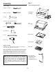
Assembly Step 1 Check package contents Tools needed Regular screwdriver Cooking box (assembly) Phillips screwdriver Hammer 7/16 inch or an adjustable wrench Lid (assembly) ® ® Pliers Tape Measure Bottom tray Pencil Electric drill Control panel Supplies needed You will need a soap and water solution to check for gas leaks. (See Step "Check for gas leaks.") Work table Note - The hardware size of nuts, bolts, and screws is given.
Front Panel Left frame Cooking grate (2) Right frame Catch pan holder Side frame (2) Catch Pan Accessory rack Drip pans (2) Warm-Up Basket Thermometer Warming Rack Condiment basket Five long Flavorizer Bars Side burner assembly Eight short Flavorizer Bars Burner grate Side panel (2) Side burner knob Base panel Side burner locks (2) Note: The locks are taped to the inside of the side burner lid.
Check contents of hardware packs Ten plastic buttons Three burner control knobs End bracket Three tool holders Three tubing plugs Two Phillips screws/washers Manifold bracket Two hinge pins (hardware size: 1/4 x 1 1/2 inch clevis pin) (actual size) One 1/4-20 x 2 inch bolts (actual size) Six 1/4-20 x 1/2 inch bolts (actual size) One 1/4-20 keps nut Seven nylon washers (actual size) Two hair pin cotters (actual size) 12
Step 2 Step 3 Assemble the frame Continue frame assembly You will need: left frame, right frame, two nylon washers, two 1/4-20 x 1/2 inch bolts and a 7/16 inch wrench. You will need: frame assembly, two side frames, four 1/4-20 x 1/2 inch bolts, four nylon washers and a 7/16 inch wrench. Note - Work on carpeted area (on grass, or on one of the boxes) to protect the finish during frame assembly.
Step 4 Step 5 Install side burner locks Measure and drill holes Note: The locks are taped to the inside of the side burner lid. You will need: Completed frame assembly, base panel, tape measure, and pencil. You will need: frame assembly, two side burner locks and a 7/16 inch wrench. CAUTION: Combustible materials should never be within 24 inches of the top, bottom, back or sides of the barbecue. Do not locate under overhead combustible construction. Turn frame assembly right side up.
Step 6 Typical installation of the base for an existing concrete patio, new pad or wood deck (continued) Typical installation of the base for an existing concrete patio, new pad or wood deck Method 1 - Concrete CAUTION: Combustible materials should never be within 24 inches of the top, bottom, back or sides of the barbecue. Do not locate under overhead combustible construction. A strike anchor, a minimum size of 3/8 inch x 3 1/2 inches long with a 3/8 inch flat washer and 3/8 inch nut. Figure 7.
Method 2 - Concrete Method 3 - Concrete A concrete lag bolt, a minimum of 3/8 inch x 2 1/2 inches long with a 3/8 inch diameter long lag shield and a 3/8 inch flat washer. Figure 8. A 3/8 inch machine screw anchor, using a 3/8-16 x 1 1/2 inch machine screw and a flat washer. Figure 9. Note - Use a 3/4 inch diameter concrete drill bit for drilling the hole for the screw base. The machine screw anchor requires a setting tool.
Typical installation of the base for an existing concrete patio, new pad or wood deck (continued) Step 7 Method 4 - Wood deck Fully tighten the 1/4-20 bolts in the frame assembly, that you only started in Step “Continue Frame Assembly” Figure 12. Tighten all frame bolts After assembling the base according to the assembly instructions, position the base assembly on your deck for anchoring. CAUTION: Combustible materials should never be within 24 inches of the top, bottom, back or sides of the barbecue.
Step 8 Add cooking box Your Weber Gas Barbecue burner assembly has been factory assembled, pressure and flame tested. As a safety precaution we recommend you check the burner alignment: You will need: cooking box assembly, 1/4-20 x 2 inch bolt, nylon washer, 1/4-20 keps nut, pliers and a 7/16 inch wrench. a) Are the ends of the burners under the washers at the left rear and left front of the cooking box? The screws are only guides. Do not tighten. Figure 15 (a).
Step 9 Step 10 Install igniter Connect barbecue gas supply line to the natural gas supply Note - The igniter wires are already attached to the Gas Catcher Ignition Chamber and the igniter. This was done to factory test the ignition system. Note - We recommend that the connection between the barbecue gas supply line and the natural gas supply be flare to flare. A 3/8-inch flare fitting has been included with the barbecue gas supply line of your gas barbecue.
Step 11 Step 12 Check all valves are off Install side burner You will need: one burner control knob. You will need: side burner assembly, burner grate, and manifold bracket. (Valves are shipped in the OFF position, but you should check to be sure.) Put the knob on each valve. Check by pushing down and turning clockwise. If they do not turn they are off. Proceed to the next step. Figure 18. WARNING: Make sure gas supply is OFF. Slide the side burner assembly into the open end of the right frame.
Step 14 Slide the side burner assembly into the open end of the right frame. Route the side burner hose so that it parallels the front of the barbecue. Loop the hose so that it reaches the side burner connection. Attach hose. Figure 20. Install burner grate. Check to be sure the side burner valve is OFF. Push side burner control knob down and turn clockwise. Figure 20. Purge air from gas lines You will need: one burner control knob.
Step 15 Check: Check for gas leaks a) Gas supply line to manifold connection. Figure 25 (a). b) Manifold to side burner hose connection. Figure 25 (b). DANGER Do not use an open flame to check for gas leaks. Be sure there are no sparks or open flames in the area while you check for leaks. This will result in a fire or explosion which can cause serious bodily injury or death and damage to property.
Step 16 Step 17 Add base panel Install side panels You will need: Base panel. You will need: two side panels, and eight plastic buttons. Put the right side in and down, tilt and set the left side in place. Figure 26. From the inside of the frame assembly, set the left side panel in place between the side frame legs. Notice that there are two sets of holes in each side panel. Align the holes in the side panel to match the holes in the left side frame legs. Push in the four plastic buttons.
Step 18 Step 19 Install Flavorizer Bars and Cooking Grates Install the bottom tray You will need: five long Flavorizer Bars, eight short Flavorizer Bars and two cooking grates. You will need: bottom tray, catch pan holder, catch pan and one drip pan. Set the long Flavorizer Bars side to side in the lower position, then set the short Flavorizer Bars front to back in the upper position in the cooking box. Figure 28.
Step 20 Step 21 Install Lid You will need: lid, two hinge pins and two hair pin cotters. Add tool holders, control panel and burner control knobs Set the lid in place. Align the hinges at the rear of the barbecue. Insert hinge pins from the outside. Insert hair pin cotters into the small holes in the hinge pins. Figure 33. You will need: three tool holders, control panel, two Phillips screws/washers, a Phillips screwdriver, and three burner control knobs.
Step 22 Step 23 Secure side burner Install the condiment basket Stand to the right side of the barbecue. Slightly pull back both side burner locks. Slide the side burner toward the control panel. The locks will snap into the slots in the front and back of the side burner. Figure 35. You will need: condiment basket and end bracket. Insert one wire end of the condiment basket into the hole in the side frame. Figure 36 (a).
Step 24 Step 25 Install the accessory rack Complete accessory installation You will need: accessory rack. You will need: Warm-Up Basket, warming rack, work table, three tubing plugs, thermometer and a hammer. Rest the left end of the accessory rack on the base panel. Figure 37 (a). Insert the right hooks into the right side frame slots. Figure 37 (b). Insert one end of the Weber Warm-Up Basket into the hole in the right end of the lid and the other end into the slot in the left end of the lid.
OPERATING INSTRUCTIONS Lighting 1) Open the lid. Figure 1. Summary lighting instructions are on the control panel. 2) Make sure all burner control knobs are turned OFF. (Push each burner control knob down and turn clockwise.) DANGER 3) Turn gas supply valve on. Failure to open lid while igniting the barbecue, or not waiting 5 minutes to allow the gas to clear if the barbecue does not light, may result in an explosive flame-up which can cause serious bodily injury or death.
Manual Lighting WARNING: Do not lean over open barbecue. Keep your face and body at least one foot away from the matchlight hole when lighting the barbecue. DANGER Failure to open lid while igniting the barbecue, or not waiting 5 minutes to allow the gas to clear if the barbecue does not light, may result in an explosive flame-up which can cause serious bodily injury or death. 5) Push Front burner control knob down and turn to START/ HI.
Lighting the side burner Lighting the side burner if the main burners are lit. Figure 4. The side burner has a separate ignition system from the main cooking box. 1) Open the side burner lid. DANGER 2) Push down and turn the side burner control to HI. Failure to open lid while igniting the side burner, or not waiting 5 minutes to allow gas to clear if the side burner does not light, may result in an explosive flame-up which can cause serious bodily injury or death.
Cooking After a Period of Nonuse You can adjust the FRONT, CENTER and BACK burners as desired. The control settings High (H), Medium (M), Low (L), or Off (O) are described in your Weber cookbook. The cookbook uses these notations to describe the settings of the FRONT, CENTER, and BACK burners. For example, to sear steaks you would use (HHH) (all burners at high). Then to complete cooking you would use (MOM) (FRONT at medium, CENTER off, and BACK at medium).
Annual Maintenance If a leak persists after retightening the fitting, turn OFF the gas. DO NOT OPERATE THE BARBECUE. Contact your dealer. After a period of nonuse we recommend that you perform the following maintenance procedures for your safety. c) Side burner hose to side burner connection. Figure 5 (c). WARNING: Check gas supply line before each use of barbecue for nicks or cracking. If the gas supply line is found to be damaged in any way, do not use the barbecue.
General Maintenance Main Burner Flame Pattern Weber Spider Stopper Guards The Weber Gas Barbecue burners have been factory set for the correct air and gas mixture. The correct flame pattern is shown in Figure 8. Your Weber Gas Barbecue, as well as any outdoor gas appliance, is a target for spiders and other insects. They can nest in the venturi section of the burner tubes. This blocks the normal gas flow, and can cause the gas to flow back out of the air shutter. Figure 6.
d) Unlatch the Spider Stopper Guards and remove. Figure 11. i) To reinstall the burners, reverse steps c) through g). CAUTION: The burner openings must be positioned properly over the valve orifices. Figure 15 (a). Check proper assembly before fastening manifold in place. Figure 15 (b). Burner opening (a) Figure 11 Valve orifice e) Disconnect gas supply line and side burner. f) Remove the manifold bracket and unscrew the two wing nuts that hold the manifold to the cooking box.
Crossover Ignition System Operations If the Crossover Ignition System fails to ignite the Front burner, light the Front burner with a match. If the Front burner lights with a match, then check the Crossover Ignition System. ■ Check that both the white and black ignition wires are attached properly. Figure 17. White wire Black wire Figure 17 ■ Check that the Crossover Ignition button pushes the igniter (button) down, and returns to the up position. ■ Check to see if the igniter is loose in the frame.
TROUBLESHOOTING Problem Check Cure Burners burn with a yellow or orange flame, in conjunction with the smell of gas. Inspect Weber Spider Stopper Guards for possible obstructions. (Blockage of holes.) Clean Weber Spider Stopper Guards. (See Section "Annual Maintenance".) Burner does not light, or flame is low in HIGH position. Is natural gas supply on ? Turn on natural gas supply.
Side Burner Troubleshooting WARNING: Before attempting any troubleshooting steps, all gas controls and supply valves should be in the OFF position. Problem Check Cure Side burner does not light. Is gas supply off? Turn supply on. Flame is low in HIGH position. Is fuel hose bent or kinked? Straighten hose. Flame is very yellow in conjunction with the smell of gas, Inspect the Weber Spider Stopper Guard for possible obstructions. (Blockage of holes.) Clean Weber Spider Stopper Guard.
1 28 29 ® ® 30 2 3 4 5 31 6 32 7 33 34 35 36 37 8 38 39 9 40 10 41 11 42 12 43 13 27 44 55 14 45-49 9 15,16 50-51,49 17 18 53 19 54 20 21 22 23 24 25 26 17 38 27
Parts List While we give much attention to our products, unfortunately an occasional error may occur. If a part is missing, do not go back to the store. Call the Weber Customer Service Center toll free 1-800-446-1071 to receive immediate assistance. Have your owner’s manual and serial number of the barbecue available for reference. All items are single quantities unless otherwise specified. Parts can be ordered directly from Weber-Stephen Products Company by phone or mail.
A FINAL WORD OF THANKS you for choosing a Weber Barbecue. TOurhankfamily here at Weber has worked hard to produce the highest quality products for your satisfaction. While we give much attention to our products, an occasional error may occur. Our knowledgeable Customer Service staff is prepared to help you with any problems with parts or assembly. Call our toll free number 1-800-446-1071. For quicker service, please have your owner’s manual available for reference.