0
HD-CCTV DVR Install & User Guide HD-CCTV DVR Manual. Thank you for purchasing a Webgate Digital Video Recorder. Before installation or operation please become familiar with the user manual and other referenced manuals mentioned in the booklet. User manual, software and hardware described here are protected by copyright by law.
Introduction Warning Warning Please do not bend or press power cord by force which could lead to fire. Be careful not to pull or plug with wet hands to avoid fire or electric shock. In case of changing built-in lithium battery, it should be replaced with same brand or similar one to prevent a danger of explosion. Since old batteries could be a factor of environment contamination, please disposed of them properly. Do not throw the batteries in fire or heating units.
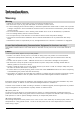
Contents Introduction 2 Warning 2 Key Features 5 Specification by Models 7 Components 8 Product Description 10 Installation 20 Connecting other devices 23 Usage 30 Default setting 31 Menu usage 36 Menu structure 36 FUNC menu 36 Monitoring 36 Search and playback 41 Playback 41 Screen composition/names of the functions 42 Copy 43 configuration 45 system configuration 45 Disk 46 Network 52 Device settings 56 Event Configuration 60 Recording set up 64 Web Viewer 67 System requirement 67 installation 67 log
Webeye 74 Mobileviewer 74 appendix 75 problem solving [FAQ] 75 compatible HDD 77 Factory default set-up values 77 Product specification 81 Product Dimension 94 4
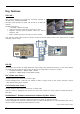
Key Features FULL HD * This product supports live monitoring, recording, playback of HD-SDI video of 1080p(1920x1080). Records 5 seconds before an event and records up to 30fps per channel. HD-SDI video record - HD 1080p : 480fps recording Supports manual & schedule recording at all times.
RAID 1/5/10 Levels * Supports RAID. Via RAID MANAGER, various RAID Levels can be configured without additional RAID devices.(RAID 1/5/10) Surveillance Screens Every channel will display HD streams without interruptions and will offer many different types of screens. Various Surveillance Screen Mode - Single, Multi Screens (1,4,9,10,13,16,CustomA,B,C) * Auto Screen Sequence Event Pop-up Voice Recording Supports real time voice input and recording function.
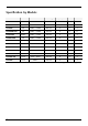
Specification by Models Model CASE HDD Recording PoC/CoC/DR NS04R RAID HD1600F-PDR Full SATA*5 + eSATA 480 FPS O O O HD1600F-R Full SATA*5 + eSATA 480 FPS X O O HD1600F Full SATA*5 + eSATA 480 FPS X O X HD1600M-PDR Full SATA*5 + eSATA 120 FPS O O O Middle SATA*2 + eSATA 120 FPS X X X HD800F-PDR Full SATA*5 + eSATA 240 FPS O X O HD800F-R Full SATA*5 + eSATA 240 FPS X X O HDC801F-PD Middle SATA*2 + eSATA 240 FPS O X X HDC801F Middle SATA*2 + eSAT
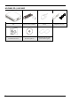
Components Please check the below to make sure you have every part.
HDC400F-PD / HDC400F 9 DVR Remote Control & Batteries Rack Bracket & Screws SW & user guide CD Mouse Installation and user guide Quick installation guide adaptor & power cord
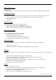
Product Description HD1600F-PDR / HD1600F-R / HD1600F / HD1600M-PDR HD800F-PDR / HD800F-R / HD400F-PDR Front view function description part name 1 2 3 4 5 6 7 8 9 10 Jog shuttle Use to control fast forward/rewind FPS rate. touch channel button Touch to select channels from live-streams and playback list. channel LED Shows input status of a stream and event movement status.
HD1600F-PDR HD1600M-PDR / HD800F-PDR / HD400F-PDR * Rear view No input/output terminal name function 1 Power In AC100V~AC240V power cord socket. 2 Sensor IN External sensor input terminal 3 Relay Relay connect terminal 4 COM2,3 5 RS-485 6 Ground connection Connection terminals that connects DVR to an outside device 7 Channel input Input connection terminal for BNC of a HD-SDI camera 8 Audio input Audio input connect terminal. 9 Audio output Speaker output terminal.
No input/output terminal name function 6 Ground connection Connection terminals that connects DVR to an outside device 7 Channel input Input connection terminal for BNC of a HD-SDI camera 8 Audio input Audio input connect terminal. 9 Audio output Speaker output terminal. 10 COM1 RS-232C D-SUB.
HDC1601M / HDC801F-PD / HDC801F / HDC801H * Front view Category 1 2 3 4 5 6 7 8 9 Function Power To turn On/Off power Touch channel button Select channel by touch during live and playback. Channel LED Shows image input status and event working status.
HDC1601M Rear view No input/output terminal name function 1 Power In AC100V~AC240V power cord socket. 2 Sensor IN External sensor input terminal 3 Relay Relay connect terminal 4 COM2,3 5 RS-485 6 Ground connection Connection terminals that connects DVR to an outside device 7 Channel input Input connection terminal for BNC of a HD-SDI camera 8 Audio input Audio input connect terminal. 9 Audio output Speaker output terminal. 10 COM1 RS-232C D-SUB.
No input/output terminal name function 3 Relay Relay connect terminal 4 COM2,3 5 RS-485 6 Ground connection Connection terminals that connects DVR to an outside device 7 Channel input Input connection terminal for BNC of a HD-SDI camera 8 Audio input Audio input connect terminal. 9 Audio output Speaker output terminal. 10 COM1 RS-232C D-SUB.
HDC400F-PD / HDC400F Front view Category Function Touch channel button Select channel by touch during live monitoring and playback. Channel LED Shows video input status and event working status.
No In/Out port name Function 3 Relay Relay Connection terminal. 4 COM2 RS-485 device connection 5 COM1 D-SUB connector for RS-232C 6 HDMI Video output HDMI connector for monitor 7 AUDIO IN RCA connection for Audio input 8 HD-SDI IN BNC connectors for camera input 9 ETHERNET RJ45 connector for network 10 eSATA eSATA connector for external storage 11 GND Ground between DVR & external device.
Remote control Can use every function of the DVR and control several DVRs with only one remote control. To be able to use the remote control, please create a user ID on the remote control ID section of system settings.
Remote control B 19
Installation Check settings This DVR is high quality security device with a high capacity built-in HDD and important curcuits. Before installation, please read carefully below recommendations as high internal temperature of the product can lead to damages and shorten product life cycle. Recommendations on installing a DVR in a rack. 1. 2. 3. 4. Don’t seal the inside of rack where DVR is installed. Keep airflow through inlet and outlet.
HDC1601M / HDC801F-PD / HDC801F / HDC801H 1. Tighten the both side of HDD bracket using screws. 2. Install HDD bracket with HDD into DVR then hold it with screw to fix it to the bottom part of DVR. Socket arrangement of SATA cable in main b’d is as follows. Two HDDs can be installed in DVR. Main b’d socket Disk manager INT A INT A INT B INT B eSATA eSATA HD1600F-PDR / HD1600F-R / HD1600M-PDR / HD1600F HD800F-PDR / HD800F-R / HD400F-PDR 1. Unscrew bracket screws that are fixing it to a DVR.. 2.
3. Lift HDD bracket to a direction shown in the right picture and separate from the bottom. 4. Place HDD in a HDD bracket and fasten 4 screws on each side. 5. Place HDD bracket fastened with screws in DVR and fasten it on the bottom with screws. Below is SATA cable socket sequence of a mainbaord. Up to 5 HDDs can be installed inside DVR.
Connecting other devices Basic connections Connecting a monitor Check monitor resolution and connect to DVR. HDMI Port : 1920 x 1080p Only connect cameras that support HD-SDI standard. We strongly recommend using HDMI certified cable when connecting to DVR. Connecting a Camera Use recommened coaxial cable to connect HD-SDI camera to DVR as shown in the picture. Only cameras with 1080p resolution can be used.
Transmission distance of the chosen cable will be various based on reduction rate of 750MHz (reduction rate of dB/100m < 25dB is recommended) Foamed or high-foamed trishield cable is recommended. Impedance 75Ω must be used for coax cable connection and connector work. Beware of deformation of cable due to high pressure over the cable. Don’t pull the cable with too much force. For DVR input/output, cables will be tied at the rear of the rack.
1) Use Gigabit Ethernet Cable(Category-6) for Network cables to connect to DVR. Other cables are not compatible with Webgate DVR. 2) NS04R and DVR must be connected by cables and normal operation isn’t guaranteed if Hub is used. Set ID configuration Set ID using Rotary switch located at rear panel. Set each different ID in case of over 2 NS04Rs are connected. Using tool such as Driver to set ID. For Group ID swich, it is set as ID in a unit of 10 when ID switch of NS04R is in a unit of 1.
Performance Connection method Available input pulse range Output current Connect the trimmed wire to terminal block Minimum 500ms Standard DC 12mA Connecting sensor input terminal Please see the picture for sensor input. The below picture is an example of connecting Dry Contact sensor type. Please refer to “Wire Handling” for more information. Connecting relay specifications Please see the below table for alarm output requirements. Output Ch.
As shown in the picture, for a set up to connect COM1/RS232 (D-Sub 9pin), set up serial & text info under “device” menu. Connecting COM2/COM3 serial port external device Connecting serial communication terminal for PTZ device & Keyboard device Control PTZ devices and Keyboard devices by connecting them to DVR’s COM ports. Picture in the right shows how a camera and a keyboard device with PTZ function are connected to RS-232 COM1 & RS-485 COM2 respectively.
The below diagram represents configuration of multi DVRs with PTZ(DOME). To control PTZ(DOME) using keyboard, please select DVR ID then select camera for control.
Serial Cable Video Cable COM2 or COM3 DOME 1 DOME 2 DOME 16 DOME 17 DOME 18 DOME 32 DOME 33 DOME 34 DOME 48 DOME 240 DOME 241 DOME 255 DVR 1 DVR 2 Master DVR 3 DVR 255 Slave 1 29 Slave 2 Slave 255
Usage Menu Structure Press [MENU] key on front panel or click [Main Menu] button under FUNC menu to enter the setup menu. To exit menu, press “X”. Main Menu Main menu The selected tab is shown in bright color and the sub-menu box will show the chosen To move to the previous/next tab, use the [◀/▶] arrow buttons. To move to a chosen submenu press the [Enter] key or click on the menu you want to view if you’re using a mouse.
Default setting Check video When turned on, DVR starts booting automatically and shows screen after the booting. If user password is set, a box will appear to enter the password, and only numbers(channel) can be entered in the box.(It is not a default setting by factory Date & Time settings Menu system date/time Standard time zone Use the left or right arrow key on the front or the mouse wheel to select your time zone.
Recording configuration menu recording recording [continuous recording] [manual recording] [schedule recording] Continuous recording Continous recording will automatically begin after the booting is completed and continous/event recording will begin according to the chosen program values. Manual recording Push REC button on the front to begin/end manual recording and manual/event recording will begin according to the chosen program values.
Use of Input/Output device Setting sensors menu event sensor Please set each and every sensor. Select a sensor, and select a type and click [save] to complete the setting. Relay setting menu event event Select from normal event group, “sensor, motion detect, text, Video Loss” or system event source group, “Disk error, Disk full, Fan error, authentication fail, WRS registration fail, Mirroring fail, abnormal Recording stop” to run relay. Also, user can set working condition by schedule.
PTZ Menu device PTZ At PTZ menu, PTZ’s serial port per each channel, Protocol, PTZ address and Baudrate can be configured. Additionally, PTZ home function, Idle time, Parity bit, Stop bit can be configured. HDD registration and format menu system disk After mounting HDD and booting, “Disk Manager” will run automatically as shown in the right picture. If it doesn’t run, please check the connectivity of HDD (1) Select a HDD among listed HDDs. Activate the HDD and execute format.
Network configuration menu network network Ethernet Click Ethernet for type and enter given IP, Netmask, Gateway, DNS. xDSL (PPPoE) Change Network menu type to xDSL then go to xDSL menu. Enter ID and Password assigned from PPPoE registration on xDSL menu. Connection confirmation message will appear when xDSL connection is secured. DDNS If DVR is using dynamic IP, use DDNS function to get domain name to access to network regardless of IP change. Enter domain name on DDNS menu.
Menu usage Menu structure Refer to the below picture for The menu structure and read the explanation in each box per item for a set-up guide. FUNC menu To run Function menu, please, click the right button of mouse in live monitoring or playback status or push “Func” button on the front panel. The Function menu enables every function of the product to be controlled by a mouse. Each function can be executed by clicking left button of mouse.
single screen click the channel number you want to view or click the left mouse button. Click [MULTI] button or click the left mouse button again to o return to multi-screen . Multi screen Click [MULTI] for multi-screen display or press multi under func menu to choose multi-screen mode. Screen description The status bar from monitoring screen shows DVR’s current status which includes the following: Date/Time, Record status, Motion Detection, sensor input status, text input, Manual Record.
Enlarged screen Using D-Zoom on a single screen, users can enlarge the section they want to view.. Click on [Zoom] button or icon in single / full screen or [FUNC] button then select Zoom button to activate Zoom mode. To expand or reduce, please use +, - button or use mouse wheel drag. The initial location of the enlarged screen is the center. Use the direction keys to move the enlarged image 22 steps to left/right and 14 steps up/down. Enlarge mode can be used between 1.00X ~ 10.00X range.
PTZ When PTZ is on, through PTZ button on front or PTZ buttons under FUNC menu, users can use pan/tilt, zoom, focus, aux and preset functions. Focus Click “near”, “far” buttons to focus. zoom click “In”, “Out” buttons to create a preferred focal point. pan/tilt pan/tilt function for PTZ configuration channel Use “Up”, “Down”, “Left”, “Right” to control pan/tilt. Loading preset Used to move to set preset location. Select wanted Preset number and press [Load] button.
Bookmark Add / Edit bookmark No, Time, Channel and Memo in [Tool-Bookmark] of FUNC menu while live or playback. Run bookmark icon “ “in Search, Copy, Thumbnail to load saved bookmarks. Screen Information Setup or change display information such as channel expression, color, size, status, show/hide/auto hide in [Information-Display] of FUNC menu.
Search and playback Playback Playback with Basic Screen In monitoring mode, Press [◀/▶] button to playback the recorded video in full screen If [PLAY] button is pressed, the last playback will run at 1x speed. If [FWD] button is pressed, playback starts from 1min earlier than recent time at 1x speed. If [REW] button is pressed, reverse playback starts from 30 second earlier than recent time at 1x speed. If [PLAY] button is pressed in multi screen mode, playback will start in multi screen mode.
Screen composition/names of the functions Screen composition name function description 1 Playback button Use buttons to control the playback. 2 screen Displays the playback videos. log viewer Displays the log seen on timeline Calendar/time search Select a date on the calendar to view the data of the date. timeline Displays the info of the unit and search the playback sections. 3 4 Icon function description buttons description Use to move to live mode. Use to COPY Used for multi-screen mode.
Time search Enter the date and time you want to search and press enter to move to the entered date and time. Calendar search When calendar search is run, it marks the dates on which there were recordings. Select a date from calendar you want to search, and it moves to that date. Event search Event info(All, Motion, Sensor, Text, None) is shown on timeline. Select a list to move to the selected time.
EXE Use USB stick to back up and use mini player or control center to playback. It is possible to select a part of channels depending on the choice of the channel list made by a user. Name function description type Select EXE using direction keys or mouse wheel. channel Press enter on a channel or right click a mouse to select a channel. (Select All : select all channels / Reset : cancel the selection of all channels) Format a USB stick before copying. Press Format or right click a mouse to begin.
configuration system configuration Please set time/disk/authority. date/time menu system date/time Set the product time in order to set recording settings. It is very important for DVR to have the right time zone in which it is used for protection of recorded videos. Default time zone is set at ‘UTC 00:00 Dublin”. Time settings Under recording, if a user changes time when it is already recording(saved in HDD), it will change the time of the previously recorded videos.
NTP menu system date/time Network Time Protocal(NTP) NTP (Network Time Protocol) synchronizes the time of all connected device. To set DVR time to standard time open server which offers standard time on the network and client which is connected to open server to receive time and synchronize it with standard time. Besides that DVR can be set as server to offer standard time to other devices and can be set as both server and client as well.
Recorded part for 2 days. Record during 10 days. Start record In progress of record Record during 10 days. Start record [Picture 1] In progress of record [Picture 2] Data deletion This function allows only recordings of preassigned date to be viewed. For example, if playback block is set at 3 days, then DVR will only save data for 3 days and will delete data more than 3 days old even if auto-deletion isn’t on. Once deleted, it can’t be restored so please be extra careful.
RAID manager menu system disk RAID manager This is the menu that manages RAID of internal HDD and HDD installed in NS04R. Steps to configure RAID 1) Select “NO” to all HDD activate in “Disk manager“ 2) Select device of creating RAID (DVR/NS04R) in RAID MANAGER“ 3) Select RAID Level(1/5/10) after selecting RAID members.
User settings menu system user settings DVR users will either be manager or user. Managers can use all functions of DVR without limitation and can set up user settings. Up to 10 users can be registered and each user can only use functions for which they’ve been given access to. Channel Rights A manager has an access to every channel. A manager can give access to channels to each user. Function access “Admin” has the rights to all the functions.
utility menu system utility Utility sets up DVR name, remote control ID, and language. DVR alias Set the DVR alias when connected to network. language select a language for a system. DVR keyboard ID This menu sets the address of keyboard when using all functions of DVR by keyboard. default value is “1”. If user wants to control various DVR by one keyboard, its address should have different value. If designated address is configured the same as keyboard, user can control DVR function.
Configuration Import/Export Export – Saves Configuration data in DVR to USB Import – Apply exported Configuration data to relevant DVR or another DVR. Recording status Displays DVR recording status.
Network Configure network info when DVR is connected to a network. Network settings menu network network Ethernet used to configure the relevant network info when DVR is connected to network. type Select Network type(Ethernet/xDSL). If DVR is connected to cable modem or lan, select “Ethernet. If DVR is connected to xDSL, PPPoE type, select xDSL. But if it is not PPPoE type, even if it is xDSL, select ‘Ethernet’.
Bandwidth limitation. Bandwidth is to configure the maximum transmission speed. Its default value is unlimited and users don’t have to set bandwidth value if there is no need to limit the network data size of DVR. Please consult DVR manager if you want to modify bandwidth value. RTSP It is short for Real Time streaming Protocol) and streams real time live image of DVR Authentification On: Only authorized users can view RTSP video. Authentification Off: Non-authorized users can view RTSP video.
DDNS menu network DDNS Through Webgate’s own DDNS service, WNS server, users can give a domain name to DVR. Using a PC, users can register for a membership and create a domain name even if they don’t register at www.mycam.to. If connected to DDNS correctly, users can connect to status and print connection successful message. If users choose to use Custom instead of WNS, they can register a domain name at www.dyndns.org or www.no-ip.org.
xDSL menu network network xDSL DVR is connected to xDSL line and use PPPoE type, please change type by xDSL and configure user ID and Password. User ID and Password should be same as xDSL. User ID/Passwor Configure user ID and Password when DVR is connected to xDSL. Status It shows connection status of DVR. Radius menu network RADIUS Radius function manages many DVR accounts with one account using Radius server. Radius menu configures status, IP address, and port.
Device settings In Device setup, user can configure camera, monitor, audio, text, serial which are connected to DVR. Camera menu device camera At this menu, user can assign [camera name], and set each camera to use or not to use. If the operator do not want live monitoring and recording for the video connected channels, the channels must be set as nonuse. PoC Status* Check the status of PoC camera & PoC adapter that are connected to DVR.
PTZ ETC Preset, Auxiliary and home time can be set up Preset Name and value of preset can be set. Up to 16 presets can be registered. Auxiliary Name and value of auxiliary can be set. Up to 16 auxiliaries can be registered. Etc • Home time: In case there is not PTZ control for the selected interval, it moves to PTZ home that was previsouly set in PTZ camera.
Monitor menu device monitor Configure SEQ, MULTI and event pop up. alarm pop-up If specific channel uses MD, Sensor Input, it makes the relevant channel pop-up as single or multi screen. To use this function, event should be set to event schedule in recording set up and MD / Sensor configuration should be done also. If event popup time is configured “off”, event popup will not work. Event pop-up can be configured per second from 1 to 10 seconds.
audio menu device audio Configure audio channel, audio recording, volume, synchronization, mixing on this menu. Audio channel Slelect a channel for audio. Video channel Configure if selected audio will be synchronized and heard through the video channel. For example, if audio channel 1 is synchronized with video channel 4, then audio will be heard through video channel 4. Save audio If users want to save the audio in use.
Time out If configured line is not full, after the last information, if there is no further information during certain time range, system deal with it as one information. Event Configuration Event menu event event Event set up has 4 set up procedures, event, motion, sensor, and preset. event configures time range with event synchronization and can be configured as off, always, and custom “always” recognizes and reacts to event when it is configured.
sync event Configuration for Event synchronization Relay When events that have been selected in “Event Sources” occur, event notification by relay goes on for the time period set in “Action time” Buzzer Event notification by buzzer goes on for the time period set in “Action time”.
E-Mail Configuration Recipient Address Input E-mail address with receiver’s E-mail info. E-mail format should be xxxx@xxxxxx.xxx and the users must only use combination of numbers and the English letters Sender’s E-mail address Sender’s E-mail address is set when user use E-mail for output selection and user setup E-mail address as xxxx@xxxxxx.xxx. Picture attachment When sensor, motion detector and video loss occur, relevant event info with channel video will be sent to an e-mail.
Motion detection menu event motion The Motion detection can be used to notify user of detected motion on each channel or all channel. Channel Configure All or each channel. Sensitivity Sensitivity can be configured from min.1 to max 10. Area Area configure detection when a motion is triggered. User can select all or clear all. In case of configuring each channel, it is available to set all, clear all or define user area. user area When selecting a channel, user area can be configured.
Recording set up There are 4 modes for recording – schedule recording, manual recording, Continuous Recording, and Event Recording. Schedule Recording records automatically in accordance with the configured schedule and Manual Recording records via pushing “REC” button. Continuous Recording records continuously upon initial system boot up. Event Recording records when an event occurs Recording menu record record Users can select the recording mode from manual, continuous, or schedule recording.
Schedule recoding It records according to the programmed schedule automatically. select “Schedule record” and configure day and time Check and select each program default value and select one of 9 programs from A to I. User can not set two different program to one schedule. Configuration Configure a program, time on a date and the info will automatically be displayed on the graph.
program menu recording program Using [Program], adjust frame rate and quality configure recording program for Continuous, Manual, and Schedule recording. Select Program to configure frame rate & resolution. For maximum performance, user can freely allocate the recording resource per channel. This feature enables the user to lower the recording performance of each channels and allocate the remaining resources to raise the recording performance of a specific channel or channels.
Web Viewer WebViewer is Web application program loaded to monitor real-time image or to monitor the images recorded through Web browser to PC located remotely. System requirement Recommendation Items CPU Core i5 3.0GHz Main Memory Video Memory 4GB 512MB or higher Display BUS 1024MB PCI-E Graphic Card Support AGP Accelerate Support PCI-E 16X or highter Network OS 100/1000 Ethernet NIC Windows XP Professional(SP3 or higher) / Windows 7 Browser Others Internet Explorer 8 or higher DirectX 9.
Monitor When it is authorized with User ID & Password input at Login page, it moves to monitor page. At Monitor page, monitor real time image of cameras connected to DVR, or it can control PTZ camera, Relay, and use Microphone function according to user’s authorization. screen division and changing video position The first monitor page will display the maximum screens of the connected model. It can to change to 1, 4, 9, 13, 16, 25, 36 divisions by clicking the number on top of page.
channel On/Off It is On/Off button for the Channel located to left in page. Click the channel wanted to On or Off. And Default is “On”. Sensor indication The icon indicates when sensor occurs in system When it sensors, relevant sensor icon comes to Red, and indicates sensor number of video. When sensor is not triggered, icon keep as blue. Relay operation It can On or Off Relay of the unit. Click the number button to activate Relay On, then the icon Changes from Blue to orange color.
If “Rec Stop” is pressed by clicking right mouse button, recroding stopped. Then, open the dialogue box to store recorded files. At this time, user can save it to the directory with any file name by user. Saved recording file is saved into “*.re4” file format. re4 file can playback through Control Center Playback program or Mini Player program. saving video There are 3 types for saving Video - jpg, bmp, eye, saving means the function to record 1 frame of current monitoring channel.
Using Audio In case of Channel setup sync with Audio, press right mouse button on the image to activate pop-up menu to “Listen” and uncheck Mute. Audio Volue adjustment is available using slide bar. Playback This page is to playback recorded images, and user who has authority of ‘HDD’ among user ID or administrator can use this function. Playback that is made up 16 divisions can play the images by searching through colander by recording period and moving the period.
bmp file. Print Select image with mouse for the channel to print image saved, and then click ‘Print’ button. Window comes to input Memo, and click ‘OK’ button to print the image through the printer connected. Print material includes ‘Printing Date’, ‘Channel name’, ‘Recording Date’ ‘Event’, ‘Memo’. Back up There are re4 (Multi channel) and avi(single channel) Set From, To time and select the channel for backup Point out the location for backup. Input in Password/Verify.
Calendar search Recorded date is enabled in black color, and others unrecorded date disabled in grey. Click [Go to] button after select date & time so as to playback images on the date & time selected. ‘When clicking the ‘Go To’ button, it indicates for 24hours from the time selected at left bottom. As above picture, it is possible to change the time zone with ‘24h’ button. Function buttons on the bottom of an image ① Indicates playback range of recorded image.
JAVA Viewer Java viewer, similar to Safari, Crome, Firefox, is a web viewer which lets users access to and monitor DVR on web-browsers which don’t support ActiveX provided by Microsoft Internet Explorer. Java should be installed in login screen to use Java viewer After installing Java manually, input IP address and port on the browser then log in by clicking Java After the login, single screen of video channel 1 is displayed. Multi-screen display, Event, Relay can be used in Java viewer.
appendix problem solving [FAQ] solution problem & symptom If system power isn’t on, LED on the Check the power of system system front won’t operate Check power voltage in out Check or replace power supply if power doesn’t turn on after above procedure No video on some channels with black screen Check the camera connected with relevant channel. Occasionally, the symptom may occur if camera video doesn’t input correctly. Check if power is supplied to camera correctly.
detection/Video loss) – It erases alarm output. 3) For event cancel : Event record mode - Alarm (Motion detection/Video loss) – It turn off mode. No response in Live screen even [PTZ] button is pressed. External HDDs are not recognized as Check if connected protocol and other configuration is set correctly for PTZ camera in Menu -> Network -> Remote Device. It takes time to be recognized multiple external HDDs. Try it again quantity installed physically after later.
will become high accordingly so HDD capacity will be reduced too. It will lead to short period time of recording Remote control doesn’t work. Point to remote control receiver Get new batteries. compatible HDD Please ask to seller for the HDD list compatible with DVR.
xDSL DDNS WRS Radius IP Address 192.168.0.2 Net Mask 255.255.255.0 Gateway 192.168.0.1 UPnP Port Forwarding off DNS 4.2.2.1 / 0.0.0.0 / 0.0.0.0 Port 80 Bandwidth Limit (Mbps) unlimited ID Guest Password ******** Status xDSL is not connected activate Turn off status Not registered URL mycam.to group none Enable off Status Not registered WNS (mycam.to) On Custom DDNS off Domain None Enable Off IP Address 0.0.0.
Recording Etc Manual Off Parity bit none Stop bit 1 Data bit 8 Header check off header 1 None header 2 None delimiter 0D0A Time interval(ms) 1000 # of lines 20 Evnet activate Turn on Event check Event synchronization always Relay 1 relay 2 Relay 3 Relay 4 buzzer Event Email FTP E-mail configuration FTP configuration 79 Turn on Normal event source turn off all system event source Turn off all Duration period 10 seconds Turn on Normal event source Turn off all system e
Motion Sensor Preset channel Cam1 activate Turn on Sensitivity 5 Area All Select activate Turn on Sensor Normal Open Channel Cam1 Preset S1~S16 None Motion None Text None Record Record Record Mode Countinuous Program A Pre Event Duration 1 Post Event Duration 1 Program Program A Normal FPS 30 Normal Quality 7 Event FPS 30 Event Quality 7 * Varies between different models 80
Product specification HD1600F-PDR 81
HD1600F-R 82
HD1600F 83
HD1600M-PDR 84
HDC1601M 85
HD800F-PDR 86
HD800F-R 87
HDC801F-PD 88
HDC801F 89
HDC801H 90
HD400F-PDR 91
HDC400F-PD 92
HDC400F 93
Product Dimension HD1600F-PDR / HD1600F-R / HD1600F / HD1600M-PDR HD800F-PDR / HD800F-R / HD400F-PDR * * Varies between different models 94
HDC1601M / HDC801F-PD / HDC801F / HDC801H * * Varies between different models 95
HDC400F-PD / HDC400F * * Varies between different models 96
Open Source License Report on the Product The software included in this product contains copyrighted software that is licensed under the GPL/LGPL. You may obtain the complete Corresponding Source code from us for a period of three years after our last shipment of this product by sending email to . If you want to obtain the complete Corresponding Source code in the physical medium such as CD-ROM, the cost of physically performing source distribution might be charged.
A “covered work” means either the unmodified Program or a work based on the Program. To “propagate” a work means to do anything with it that, without permission, would make you directly or secondarily liable for infringement under applicable copyright law, except executing it on a computer or modifying a private copy. Propagation includes copying, distribution (with or without modification), making available to the public, and in some countries other activities as well.
THERE IS NO WARRANTY FOR THE PROGRAM, TO THE EXTENT PERMITTED BY APPLICABLE LAW. EXCEPT WHEN OTHERWISE STATED IN WRITING THE COPYRIGHT HOLDERS AND/OR OTHER PARTIES PROVIDE THE PROGRAM “AS IS” WITHOUT WARRANTY OF ANY KIND, EITHER EXPRESSED OR IMPLIED, INCLUDING, BUT NOT LIMITED TO, THE IMPLIED WARRANTIES OF MERCHANTABILITY AND FITNESS FOR A PARTICULAR PURPOSE. THE ENTIRE RISK AS TO THE QUALITY AND PERFORMANCE OF THE PROGRAM IS WITH YOU.
in or among countries not thus excluded. In such case, this License incorporates the limitation as if written in the body of this License. 13. The Free Software Foundation may publish revised and/or new versions of the Lesser General Public License from time to time. Such new versions will be similar in spirit to the present version, but may differ in detail to address new problems or concerns. Each version is given a distinguishing version number.
without fee is hereby granted, provided that the above copyright notice appear in all copies and that both that copyright notice and this permission notice appear in supporting documentation, and that the name of M.I.T. not be used in advertising or publicity pertaining to distribution of the software without specific, written prior permission. M.I.T. makes no representations about the suitability of this software for any purpose. It is provided "as is" without express or implied warranty.
Manufacturer might service at user’s cost for following request made by customer. 1. Customer notice. Please make regular schedule to check unit status (Daily check is recommended). Manufacturer will not take any responsibility on the physical/human damage caused by robbery, natural disaster. A/S will include product only manufactured by original manufacturer. Any damage caused during installation will be dealt with installation company.
Warranty Product name Model name Date of purchase Warranty term Serial number Digital Video Recorder HD1600F-R / HD1600F-PDR HD1600M-PDR / HD1600F HD800F-PDR / HD800F-R HD400F-PDR HDC1601M / HD801F-PD HDC801F / HDC801H HDC400F-PD / HDC400F / / / Warranty term 2 years after purchase / Customer’s address Name Contact Address of shop(Company name) Name Contact ◈ Please fill out vacant area before selling products.
104