A WILSON ELECTRONICS BRAND Home Complete Cellular Signal Booster Installation Guide NEED HELP? support.weboost.com 866.294.
______ Index Package Contents 1 Preparation 2 STEP 1-A & B: Inside Antenna & Booster Placement 3 Point Outside Antenna Toward Nearest Cell Tower & Mount 5 STEP 3-A: Route & Connect Outside Antenna To Booster 8 STEP 3-B: Route & Connect Inside Antenna To Booster 9 STEP 4: Power Up The Booster & Optimize The System STEP 2: 10 Measuring Booster Performance 12 Light Patterns 14 Troubleshooting 15 Safety Guidelines 16 Specifications 17 Warranty 21
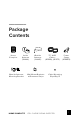
______ Package Contents Home Complete Inside Antenna (314444) Outside Antenna (314445) 75’ & 60’ Cables (951160), (951175) Outside Antenna Mounting Bracket Wall Mount Brackets w/Command Strips HOME COMPLETE CELL PHONE SIGNAL BOOSTER Power Suppy (850023) Cable Mounting Clips Qty.
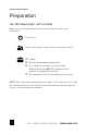
______ Preparation You Will Need (tools not included) Make sure the following materials are prepared and ready for your installation.
______ Step 1-A & B: Inside Antenna Placement Place the Inside Antenna where you need the greatest signal boost and place Booster in your desired location at least 18” away from Inside Antenna. NOTE: Do not connect booster to power until the system is fully installed. TIP: The cable from the Inside Antenna can be routed into the ceiling and connected to the coax cable out-of-sight for a better look.
______ (STEP 1-A & B cont.) The Inside Antenna can be mounted horizontal, vertical or on a desktop. Command strips can be used to secure mouting bracket.
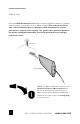
______ Step 2: Mount Antenna And Point Outside Antenna Toward Nearest Cell Tower Pole mounting and wall mounting options are included. The pole mounting option is preferred because it will be easier to adjust to the direction of the cell tower. Attach the Mount to the Outside Antenna and use the Bracket Clamps to attach the Antenna to a pole or exhaust pipe. Outside Antenna Bracket Clamps Mount Pole (1.0”-3.0”dia.) NOTE: Mounting on existing roof exhaust pipe would be a good time-saver option.
______ (STEP 2 cont.) Point the Outside Antenna toward the nearest cell phone tower. To find the nearest tower, use an app such as ‘Open Signal’. This is the most critical step of the installation process because it will determine the overall performance of the booster system. The greater the separation between the Inside and Outside Antennas, the better performance you will get from the booster.
______ (STEP 2 cont.) If there’s not a pole to easily mount the Outside Antenna, this may be mounted on the fascia by fastening the bracket as shown below. TIP: Make sure to do the optimization test on Step 4 to find the best side of your house before you mount this on the fascia.
______ Step 3-A: Route & Connect Outside Antenna To Booster Connect the black 75’ Coax Cable to Outside Antenna and route cable into the home. All connections should be hand tightened only. Cable Mounting Clips provided Outside Antenna 75’ Coax Cable Booster Route cable to the Home Complete Booster and connect to the port labeled ‘OUTSIDE ANTENNA’.
______ Step 3-B: Route & Connect Inside Antenna To Booster Connect the black 60’ Coax Cable to Inside Antenna and route to the Home Complete Booster and connect to the port labeled ‘INSIDE ANTENNA’.
______ Step 4: Power Up The Booster & Optimize The System Plug the Power Supply into wall outlet then connect to end of booster labeled “ ” (turn 90° to lock connector). NOTE: We strongly recommend using a power strip with surge protection.
______ (STEP 4 cont.) After powering up your system, you are now ready to optimize your system. Rotate the Outside Antenna in 1/4 turn increments, after each turn, unplug and reconnect the booster to power while observing the signal level on your cell phone from the Inside Antenna’s projected area. Secure the Outside Antenna in place, pointing in the direction that gives you the strongest signal.
______ Measuring Booster Performance How To Get Signal Strength As A Number iPhone® iOS 11 and later no longer displays the decibel (dBm) reading in ‘Field Test Mode’. Tip: Using the dot signal strength indicator on your cell phone can assist you in finding the strongest signal direction as well as placing calls in different locations. For changes/updates on this issue, periodically go to weboost.com/signalstrength.
______ (MEASURING BOOSTER PERFORMANCE cont.) Signal Strength without Booster Note here: Signal Strength with Booster Note here: Compare Results Having an accurate measurement of signal strength in decibels (dBm) is crucial when installing your system. Decibels accurately measure the signal strength you are receiving.
______ Light Patterns Booster lights Solid Green This indicates that your booster is functioning properly and there are no issues with installation. Blinking Green, Then Red Band 2/25 Band 4 Band 5 Band 12/13/17 Band has reduced gain. This indicates that one or more of the booster bands has reduced power due to a feedback loop condition called oscillation. This is a built in safety feature to prevent harmful interference with a nearby cell tower.
______ Troubleshooting IF YOU ARE HAPPY WITH THE COVERAGE, THESE LIGHT ISSUES DON’T HAVE TO BE RESOLVED. YOUR CARRIER’S BAND HAS NOT BEEN AFFECTED. FIXING ANY RED LIGHT ISSUES This involves Solid Red & Blinking Green/Red lights. 1 Verify Outside Antenna faces away from the Inside Antenna. Un-plug and replug in power supply. 2 Verify the Inside Antenna is at least 18” from the Booster and pointed away from the Booster. Unplug and re-plug in power supply.
______ Safety Guidelines To uphold compliance with network protection standards, all active cellular devices must maintain at least six feet of separation distance from Inside Panel and Dome antennas and at least four feet of separation distance from desktop Antenna. Use only the power supply provided in this package. Use of a non-weBoost product may damage your equipment. The Signal Booster unit is designed for use in an indoor, temperature-controlled environment (less than 100 degrees Fahrenheit).
______ Specifications Home Complete™ Model Number 460045 PWO460045 FCC ID Connectors F-Female Antenna Impedance Frequency Power output for single cell phone (Uplink) dBm Power output for single cell phone (Downlink) dBm Noise Figure 75 Ohms 698-716 MHz, 729-746 MHz, 777-787 MHz, 824-894 MHz, 1850-1995 MHz, 1710-1755/2110-2155 MHz 1900 MHz Band 25/2 700 MHz Band12/17 700 MHz Band13 800 MHz Band 5 1700 MHz Band 4 25.14 24.69 25.06 25.15 25.
Notes NEED HELP? 18 support.weboost.com CELL PHONE SIGNAL BOOSTER 866.294.
Notes NEED HELP? HOME COMPLETE support.weboost.com CELL PHONE SIGNAL BOOSTER 866.294.
Notes NEED HELP? 20 support.weboost.com CELL PHONE SIGNAL BOOSTER 866.294.
2 YEAR WARRANTY weBoost Signal Boosters are warranted for two (2) years against defects in workmanship and/or materials. Warranty cases may be resolved by returning the product directly to the reseller with a dated proof of purchase. Signal Boosters may also be returned directly to the manufacturer at the consumer’s expense, with a dated proof of purchase and a Returned Material Authorization (RMA) number supplied by weBoost. weBoost shall, at its option, either repair or replace the product.
3301 East Deseret Drive, St. George, UT 866.294.1660 www.weboost.com support.weboost.com Copyright © 2019 weBoost. All rights reserved. weBoost products covered by U.S. patent(s) and pending application(s) For patents go to: weboost.