
Install Instructions

THERMOSTATIC MIXING VALVE
INSTALLATION &
SERVICING INSTRUCTIONS
ONE APPIAN WAY WORCESTER, MA 01610
P.O. BOX 59 WORCESTER, MA 01613
P: (800) 225-9529 • F: (800) 336-5133
www.webstonevalves.com
The Webstone TMV is designed for use in heating as well as domestic water systems and provides outlet temperatures ranging
between 95°–131° F. The valve may be positioned in any orientation; designated lengths of straight piping before and after the unit
are not required. The Webstone Thermostatic Mixing Valve is a SAFETY VALVE. Inspect the TMV at least once per year to verify it is
operating correctly. It may be necessary to check the valve more frequently in installations with poor or unknown water quality. Use
of a lter or strainer is required for installations with poor or unknown water quality.
IMPORTANT: Follow all federal/national, state and local codes when installing, testing or performing work on systems. All parts
are covered by a lifetime warranty against manufacturing defects provided they are installed by a licensed plumber and operated
under normal working conditions. Disassembling will void this warranty. If you have any questions or comments, please contact us
at (800) 225-9529 or visit us on the web - www.webstonevalves.com.
WARNING: This valve was not designed for installations exposed to subfreezing conditions; use suitable insulation if this possibility
exists in your installation. Subjecting the Webstone TMV to heat during installation may damage the valve internals. The Webstone
TMV is designed for use in water systems only. DO NOT use the TMV in steam systems. The use of excessive thread sealant may cause
the Webstone TMV to fail.
INSTALLATION
1. Prepare the system for the TMV installation:
a. Flush the system thoroughly before fi tting the Webstone TMV. It is critical to ush all debris from the pipework
before installing the Webstone TMV. This step eliminates the most common cause of system dif culties.
b. Check the speci cations of your Webstone TMV against site parameters, such as temperature and
pressure. Rectify any conditions outside the valves speci cations before installation.
2. Attach a union assembly to each end of the valve body.
Series 7520 & 7420 ONLY - Check valve ttings may only be installed on the hot and cold inlet.
3. Ensure that each union nut is aligned accurately to the valve and that washers are properly in place.
4. Connect the hot water supply line to the inlet marked HOT.
5. Connect the cold water supply line to the inlet marked COLD.
6. Connect mixed water line to outlet marked MIX, also indicated with a ow arrow.
7. Fully tighten the union assemblies at each connection.
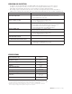
8. Set the output to the desired temperature* by aligning the numbers on the handle
with the mark on the valve body in accordance with the table below:
Handle Marking 1234
Output
Temperature
95°F
(35°C)
109°F
(43°C)
119°F
(48°C)
131°F
(55°C)
* Output temperature may vary slightly due to seasonal changes in cold water supply temperatures. Numbers on
handle are calibrated at the time of manufacture and should be used for initial commissioning of valve only.
9. Verify that the correct mixed water temperature is being achieved:
a. Open the nearest water outlet supplied by the TMV to a ow of 2 to 3 gpm. It is important to test the temperature
at the nearest outlet to ensure water delivered to any outlet is not greater than the desired maximum.
b. Allow the water to reach a stable temperature and measure.
10. Turn the handle clockwise to decrease, or counter-clockwise to increase the outlet temperature as needed.
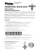
SETTING TEMPERATURE LOCK (OPTIONAL)
If desired, the temperature range can be limited on the
Webstone TMV by locking the handle in place:
1. Set and verify the mixed water temperature,
following the steps above.
2. Remove screw and handle.
3. Align Internal Pin on handle with slot on Temperature Limit Stop.
4. Replace handle and secure screw.
NOTE: Field calibration may be needed if handle
has been removed or locked.
o
p
.