OWNER'S MANUAL MODEL NO. SGT18H46C 18.0 HP 46 Inch Lawn Tractor For Parts and Service, contact our authorized distributor: call 1-800-849-1297 For Technical Assistance: call 1-800-829-5886 ® 178387 4.6.01 TR PRINTED IN U.S.A.
SAFETY RULES SAFE OPERATION PRACTICES FOR RIDE-ON MOWERS IMPORTANT: THIS CUTTING MACHINE IS CAPABLE OF AMPUTATING HANDS AND FEET AND THROWING OBJECTS. FAILURE TO OBSERVE THE FOLLOWING SAFETY INSTRUCTIONS COULD RESULT IN SERIOUS INJURY OR DEATH. I. GENERAL OPERATION • • • • • • • • • • • • • • • • • • Avoid starting or stopping on a slope. If tires lose traction, disengage the blades and proceed slowly straight down the slope.
SAFETY RULES Safe Operation Practices for Ride-On Mowers • • • • • • • • • • • • • • Look for this symbol to point out important safety precautions. It means CAUTION!!! BECOME ALERT!!! YOUR SAFETY IS INVOLVED. Be sure the area is clear of other people before mowing. Stop machine if anyone enters the area. Never carry passengers or children even with the blades off. Do not mow in reverse unless absolutely necessary. Always look down and behind before and while backing. Never carry children.
PRODUCT SPECIFICATIONS GASOLINE CAPACITY AND TYPE: 3.5 GALLONS UNLEADED REGULAR OIL TYPE (API-SF-SJ): SAE 30 (above 32°F) SAE 5W-30 (below 32°F) OIL CAPACITY: W/FILTER: 5 PINTS W/O FILTER: 4.5 PINTS SPARK PLUG: (GAP: .030") CHAMPION RN4C GROUND SPEED (MPH): FORWARD: REVERSE: 5.5 2.4 TIRE PRESSURE: FRONT: REAR: 14 PSI 10 PSI CHARGING SYSTEM: CONGRATULATIONS on your purchase of a new tractor.
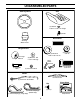
UNASSEMBLED PARTS Steering Wheel Seat (1) Washer 17/32 x 1-3/16 x 12 Gauge (1) Knob Nose Roller Steering Wheel Insert Gauge Wheels (2) Washers 17/32 x 7/8 x 16 Ga.
ASSEMBLY Your new tractor has been assembled at the factory with exception of those parts left unassembled for shipping purposes. To ensure safe and proper operation of your tractor all parts and hardware you assemble must be tightened securely. Use the correct tools as necessary to insure proper tightness. TOOLS REQUIRED FOR ASSEMBLY STEERING WHEEL INSERT A socket wrench set will make assembly easier. Standard wrench sizes are listed.
ASSEMBLY INSTALL SEAT (See Fig. 3) TO ROLL TRACTOR OFF SKID (See Operation section page 11 for location and function of controls) Adjust seat before tightening adjustment knob. • Remove adjustment knob and flat washer securing seat to cardboard packing and set aside for assembly of seat to tractor. • Pivot seat upward and remove from the cardboard packing. Remove the cardboard packing and discard. • Place seat on seat pan so head of shoulder bolt is positioned over large slotted hole in pan.
ASSEMBLY • INSTALL MOWER AND DRIVE BELT (See Figs. 5 and 6) Be sure tractor is on level surface and mower suspension arms are raised with attachment lift control. Engage parking brake. • Cut and remove ties securing anti-sway bar and belts. Swing anti-sway bar to left side of mower deck. • Slide mower under tractor with deflector shield to right side of tractor. • • IMPORTANT: CHECK BELT FOR PROPER ROUTING IN ALL MOWER PULLEY GROOVES. INSTALL BELT INTO ENGINE PULLEY GROOVE.
ASSEMBLY 3CHECKLIST CHECK TIRE PRESSURE The tires on your tractor were overinflated at the factory for shipping purposes. Correct tire pressure is important for best cutting performance. • Reduce tire pressure to PSI shown in “PRODUCT SPECIFICATIONS” section of this manual. BEFORE YOU OPERATE AND ENJOY YOUR NEW TRACTOR, WE WISH TO ASSURE THAT YOU RECEIVE THE BEST PERFORMANCE AND SATISFACTION FROM THIS QUALITY PRODUCT. PLEASE REVIEW THE FOLLOWING CHECKLIST: 3 All assembly instructions have been completed.
OPERATION These symbols may appear on your tractor or in literature supplied with the product. Learn and understand their meaning.
OPERATION KNOW YOUR TRACTOR READ THIS OWNER'S MANUAL AND SAFETY RULES BEFORE OPERATING YOUR TRACTOR Compare the illustrations with your tractor to familiarize yourself with the locations of various controls and adjustments. Save this manual for future reference.
OPERATION The operation of any tractor can result in foreign objects thrown into the eyes, which can result in severe eye damage. Always wear safety glasses or eye shields while operating your tractor or performing any adjustments or repairs. We recommend a wide vision safety mask over spectacles or standard safety glasses. IMPORTANT: LEAVING THE IGNITION SWITCH IN ANY POSITION OTHER THAN "OFF" WILL CAUSE THE BATTERY TO BE DISCHARGED, (DEAD). HOW TO USE YOUR TRACTOR TO SET PARKING BRAKE (See Fig.
OPERATION TO OPERATE ON HILLS TO ADJUST GAUGE WHEELS (See Fig. 8) Gauge wheels are properly adjusted when they are slightly off the ground when mower is at the desired cutting height in operating position. Gauge wheels then keep the deck in proper position to help prevent scalping in most terrain conditions. NOTE:Adjust gauge wheels with tractor on a flat level surface. • Adjust mower to desired cutting height (See “TO ADJUST MOWER CUTTING HEIGHT” in the Operation section of this manual).
OPERATION BEFORE STARTING THE ENGINE TO START ENGINE (See Fig. 6) When starting the engine for the first time or if the engine has run out of fuel, it will take extra cranking time to move fuel from the tank to the engine. • Be sure freewheel control is in the transmission engaged position. • Sit on seat in operating position, depress clutch/brake pedal and set parking brake. • Place motion control lever in neutral (N) position. • Move attachment clutch to “DISENGAGED” position.
OPERATION MOWING TIPS PURGE TRANSMISSION • CAUTION: Never engage or disengage freewheel lever while the engine is running. • To ensure proper operation and performance, it is recommended that the transmission be purged before operating tractor for the first time. This procedure will remove any trapped air inside the transmission which may have developed during shipping of your tractor.
CUSTOMER RESPONSIBILITIES MAINTENANCE SCHEDULE FILL IN DATES AS YOU COMPLETE REGULAR SERVICE E S S GE RS US RS UR OUR OU SON ORA U O H O H H A 0 ST E 8H SE 25 50 10 RE Y Y Y Y Y RE R R R R R O O E E F E E E F SERVICE EV EV EV EV EV BE BE H AC DATES Check Brake Operation Check Tire Pressure T R A C T 0 R Check Operator Presence and Interlock Systems Check for Loose Fasteners Sharpen/Replace Mower Blades 7 4 Lubrication Chart Check Battery Level 6 Clean Battery and Terminals Check Transaxle Cooling A
CUSTOMER RESPONSIBILITIES TRACTOR TRAILING EDGE UP Always observe safety rules when performing any maintenance. BLADE MANDREL ASSEMBLY CENTER HOLE BRAKE OPERATION If tractor requires more than six (6) feet stopping distance at high speed in highest gear, then brake must be adjusted. (See “TO ADJUST BRAKE” in the Service and Adjustments section of this manual). BLADE BOLT (SPECIAL) STAR TIRES • Maintain proper air pressure in all tires (See “PRODUCT SPECIFICATIONS” section of this manual).
CUSTOMER RESPONSIBILITIES Change the oil after every 50 hours of operation or at least once a year if the tractor is not used for 50 hours in one year. Check the crankcase oil level before starting the engine and after each eight (8) hours of operation. Tighten oil fill cap/ dipstick securely each time you check the oil level. TO CLEAN BATTERY AND TERMINALS Corrosion and dirt on the battery and terminals can cause the battery to “leak” power. • Remove terminal guard.
CUSTOMER RESPONSIBILITIES AIR FILTER CLAMP CLAMP Your engine will not run properly using a dirty air filter. Clean the foam pre-cleaner after every 25 hours of operation or every season. Service paper cartridge every 100 hours of operation or every season, whichever occurs first. Service air cleaner more often under dusty conditions. (See engine manual for instructions). FUEL FILTER FIG.
SERVICE AND ADJUSTMENTS CAUTION: BEFORE PERFORMING ANY SERVICE OR ADJUSTMENTS: • Depress clutch/brake pedal fully and set parking brake. • Place motion control lever in neutral (N) position. • Place attachment clutch in “DISENGAGED” position. • Turn ignition key “OFF” and remove key. • Make sure the blades and all moving parts have completely stopped. • Disconnect spark plug wire from spark plug and place wire where it cannot come in contact with plug.
SERVICE AND ADJUSTMENTS SIDE-TO-SIDE ADJUSTMENT (See Figs. 18 and 19) • Raise mower to its highest position. • At the midpoint of both sides of mower, measure height from bottom edge of mower to ground. Distance “A” on both sides of mower should be the same or within 1/4" of each other. • If adjustment is necessary, make adjustment on one side of mower only. • To raise one side of mower, tighten lift link adjustment nut on that side.
SERVICE AND ADJUSTMENTS CLUTCH SPRING SCREWS L.H. MANDREL COVER TO ADJUST BRAKE (See Fig. 24) SMALL RETAINER SPRING IDLER PULLEYS Your tractor is equipped with an adjustable brake system which is mounted on the side of the transaxle. If tractor requires more than six (6) feet stopping distance at high speed in highest gear on a level dry concrete or paved surface, then brake must be adjusted. • Depress clutch/brake pedal and engage parking brake.
SERVICE AND ADJUSTMENTS • On rear wheels only: align grooves in rear wheel hub and axle. Insert square key. • Replace washers and snap retaining ring securely in axle groove. • Replace axle cover. NOTE: To seal tire punctures and prevent flat tires due to slow leaks, tire sealant may be purchased from your local parts dealer. Tire sealant also prevents tire dry rot and corrosion. TRANSAXLE MOTION CONTROL LEVER NEUTRAL ADJUSTMENT(See Fig.
SERVICE AND ADJUSTMENTS REPLACING BATTERY (See Fig. 29) TO REMOVE HOOD AND GRILL ASSEMBLY (See Fig. 30) CAUTION: Do not short battery terminals by allowing a wrench or any other object to contact both terminals at the same time. Before connecting battery, remove metal bracelets, wristwatch bands, rings, etc. Positive terminal must be connected first to prevent sparking from accidental grounding. • • • • • • • • • • • • • HOOD Lift hood to raised position. Remove terminal guard.
STORAGE Immediately prepare your tractor for storage at the end of the season or if the tractor will not be used for 30 days or more. ENGINE FUEL SYSTEM CAUTION: Never store the tractor with gasoline in the tank inside a building where fumes may reach an open flame or spark. Allow the engine to cool before storing in any enclosure. IMPORTANT: IT IS IMPORTANT TO PREVENT GUM DEPOSITS FROM FORMING IN ESSENTIAL FUEL SYSTEM PARTS SUCH AS CARBURETOR, FUEL FILTER, FUEL HOSE, OR TANK DURING STORAGE.
TROUBLESHOOTING POINTS PROBLEM CAUSE Will not start 1. 2. 3. 4. 5. 6. 7. Out of fuel. Engine not “CHOKED” properly. Engine flooded. Bad spark plug. Dirty air filter. Dirty fuel filter. Water in fuel. 1. 2. 3. 4. 5. 6. 7. 8. 9. Loose or damaged wiring. Carburetor out of adjustment. 8. 9. 10. Hard to start CORRECTION Engine valves out of adjustment. 10. Fill fuel tank. See “TO START ENGINE” in Operation section. Wait several minutes before attempting to start. Replace spark plug.
TROUBLESHOOTING POINTS PROBLEM CAUSE CORRECTION Engine continues to run when operator leaves seat with attachment clutch engaged 1. Faulty operator-safety presence control system. 1. Check wiring, switches and connections. If not corrected, contact an authorized service center/ department. Poor cut - uneven 1. 2. 3. 4. 5. Worn, bent or loose blade. Mower deck not level. Buildup of grass, leaves, and trash under mower. Bent blade mandrel.
SERVICE NOTES 28
TRACTOR - - MODEL NUMBER SGT18H46C SCHEMATIC RED BLACK BATTERY RED A RED FUSE AMMETER (OPTIONAL) M STARTER BLACK WHITE SOLENOID RED B S G BLACK L M CLUTCH / BRAKE (PEDAL UP) A1 A2 WHITE SEAT SWITCH (NOT OCCUPIED) IGNITION SWITCH WHITE BLACK BLACK BLACK BLACK HOUR METER ATT'MENT CLUTCH (CLUTCH OFF) GROUNDING CONNECTOR (OPTIONAL) BLUE SPARK PLUG GAP (2 PLUGS ON TWIN CYL.
REPAIR PARTS TRACTOR - - MODEL NUMBER SGT18H46C ELECTRICAL 21 22 42 24 41 43 27 27 40 26 27 27 25 16 16 33 30 10 D.C 11 .
REPAIR PARTS TRACTOR - - MODEL NUMBER SGT18H46C ELECTRICAL KEY NO. PART NO. DESCRIPTION 1 2 8 10 11 12 16 21 22 24 25 26 27 28 29 30 33 40 41 42 43 45 55 163465 74760412 7603J 145211 150109 145769 153664 166181 4152J 108423X 146148 175158 73510400 145491 121305X 175566 140401 178446 71110408 131563 178861 121433X 17490508 Battery, 12 Volt, 28 Amp Bolt, Hex Head 1/4-20 UNC x 3/4 Tray, Battery Bolt, Battery Front 1/4-20 x 7.
REPAIR PARTS TRACTOR - - MODEL NUMBER SGT18H46C CHASSIS 119 30 24 29 36 87 17 212 36 36 24 26 25 26 25 120 121 122 31 123 44 3 90 50 19 124 28 125 71 66 9 115 209 117 64 114 209 209 3 153 6 209 209 86 209 8 11 1 59 26 114 117 209 3 35 74 33 10 3 209 2 205 35 205 3 206 108 38 13 34 38 32 26 209
REPAIR PARTS TRACTOR - - MODEL NUMBER SGT18H46C CHASSIS KEY NO. PART NO.
REPAIR PARTS TRACTOR - - MODEL NUMBER SGT18H46C DRIVE 51 57 51 89 63 69 19 197 16 61 198 161 42 16 169 171 164 21 58 48 42 40 163 38 42 166 82 146 35 165 47 62 8 110 16 51 51 139 103 30 36 120 34 110 53 28 73 110 111 142 131 95 26 29 3 27 135 26 19 77 76 189 2 136 141 36 35 37 19 102 94 96 49 39 156 110 151 51 27 168 10 138 150 41 83 14 202 50 64 56 162 134 65 159 158 19 146 116 66 31 71 70 59 81 139 72 26 77 24 129 22 126
REPAIR PARTS TRACTOR - - MODEL NUMBER SGT18H46C DRIVE KEY PART NO. NO.
REPAIR PARTS TRACTOR - - MODEL NUMBER SGT18H46C STEERING ASSEMBLY 38 38 12 39 1 41 42 37 37 36 88 91 43 71 29 67 67 68 67 46 29 8 47 6 9 17 13 65 46 85 2 8 7 85 6 9 9 5 47 7 3 32 9 5 92 11 82 29 29 4 26 43 29 29 15 40 43 15 28 15 10 36 30 6 8
REPAIR PARTS TRACTOR - - MODEL NUMBER SGT18H46C STEERING ASSEMBLY KEY NO. PART NO.
REPAIR PARTS TRACTOR - - MODEL NUMBER SGT18H46C ENGINE 106 3 2 1 107 8 14 38 13 10 81 25 105 105 6 5 16 26 45 62 99 72 32 31 45 34 100 33 37 39 40 41 33 45 23 29 OPTIONAL EQUIPMENT 4 Spark Arrester 38
REPAIR PARTS TRACTOR - - MODEL NUMBER SGT18H46C ENGINE KEY NO. PART NO.
REPAIR PARTS TRACTOR - - MODEL NUMBER SGT18H46C SEAT ASSEMBLY 1 18 28 28 14 7 7 10 5 6 22 27 2 21 24 5 16 25 15 11 13 17 12 KEY NO. PART NO. DESCRIPTION 1 2 5 6 7 10 11 12 13 14 15 140118 140551 145006 73800600 124181X 174894 166369 121246X 121248X 72050412 121249X Seat Pivot Bracket, Seat Clip, Push-in Hinged Nut, Lock Hex w/Ins 3/8-16 UNC Spring, Seat Pan, Seat Knob, Seat, Black Bracket, Switch Mounting Bushing, Snap, Black, Nylon Bolt, Carriage 1/4-20 x 1-1/2 Spacer, Split KEY NO.
REPAIR PARTS TRACTOR - - MODEL NUMBER SGT18H46C DECALS 4 11 2 2 7 3 17 17 1 12 14 8 13 6 13 10 19 KEY NO. PART NO. DESCRIPTION KEY NO. PART NO.
REPAIR PARTS TRACTOR - - MODEL NUMBER SGT18H46C MOWER LIFT 29 28 27 25 24 23 7 8 9 41 1 10 49 47 37 14 38 30 40 36 50 13 26 46 2 11 6 12 13 19 13 20 15 31 32 13 19 31 32 44 42 43 39 42 20 17 18 20 16 20 15
REPAIR PARTS TRACTOR - - MODEL NUMBER SGT18H46C MOWER LIFT KEY NO. PART NO.
REPAIR PARTS TRACTOR - - MODEL NUMBER SGT18H46C MOWER DECK 67 157 158 156 153 151 155 46 152 41 135 153 154 49 136 42 45 41 69 85 127 46 36 37 42 43 45 40 59 126 58 44 33 44 129 39 32 116 50 31 130 35 72 52 38 30 62 33 32 61 62 60 132 31 34 117 47 30 90 119 91 180 93 94 93 180 21 95 90 21 118 82 3 18 134 5 133 6 26 21 1 22 23 24 25 29 28 117 27 19 15 14 18 16 20 48 13 18 11 10 9 8 44
REPAIR PARTS TRACTOR - - MODEL NUMBER SGT18H46C MOWER DECK KEY NO. PART NO. DESCRIPTION KEY NO.
LIMITED WARRANTY The Manufacturer warrants to the original consumer purchaser that this product as manufactured is free from defects in materials and workmanship. For a period of two (2) years from date of purchase by the original consumer purchaser, we will repair or replace, at our option, without charge for parts or labor incurred in replacing parts, any part which we find to be defective due to materials or workmanship. This Warranty is subject to the following limitations and exclusions. 1.
15 MAX. SIGHT AND HOLD THIS LEVEL WITH SKY LINE OR TREE. CUT OUT ON D THIS OTT IS A ED L 15 S INES LOP E Operate your Tractor up and down the face of slopes (not greater than 15 ), never across the face. Make turns gradually to prevent tipping or loss of control. Exercise extreme caution when changing direction on slopes.
®