
Owner`s manual


SERVICE AND ADJUSTMENTS
WARNING: TO AVIOD SERIOUS INJURY, BEFORE PERFORMING ANY SERVICE OR ADJUSTMENTS:
Depress clutch/brake pedal fully and set parking brake.
• Place gearshift lever in neutral (N) position.
Place attachment clutch in "DISENGAGED" position.
Turn ignition key to "STOP" and remove key.
Make sure the blades and all moving parts have completely stopped.
Disconnect spark plug wire from spark plug and place wire where it cannot come in contact with
plug.
TRACTOR
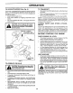
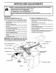
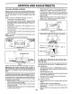
TO REMOVE MOWER (See Fig. 15)
Mower willbe easierto remove from the right side of tractor.
Place attachment clutch in "DISENGAGED" position.
• Move attachment lift lever forward tOlower mower to its
lowest position.
Roll belt off engine pulley.
Remove small retainer spring, and lift clutch spring off
pulley bolt.
• Removelargeretainerspring, slidecollaroffandpush
housing guide out of bracket.
Disconnect anti-swaybar from chassis bracket by re-
moving retainer spring.
Disconnect suspension arms from rear deck brackets
by removing retainer springs.
Disconnect front links from deck by removing retainer
springs.
• Raise lift lever to raise suspension arms. Slide mower
out from under tractor.
IMPORTANT: IF AN A37-ACHMENT OTHER THAN THE
MOWER DECK IS TO BE MOUNTED ON THE TRAC-
TOR, REMOVE THE FRONT LINKS AND HOOK THE
CLUTCH SPRING INTO SQUARE HOLE IN FRAME.
SUSPENSION ARMS
TO INSTALL MOWER (See Fig. 15)
Raise attachment liftlever to its highest position.
Slide mower under tractor with deflector shield to right
side of tractor.
Lower lift lever to its lowest position.
• Connect front links to mower deck and secure with
retainer springs.
Connect suspension arms to rear deck brackets and
secure with retainer springs.
• Connect anti-swaybar to chassis bracket and secure
with retainer spring.
• Push clutch cable housing guide into bracket, slide collar
onto guide and secure with large retainer spring.
• Install belt onto engine pulley.
SMALL ENGINE PULLEY
CLUTCH
RETAINER
LINK
ANTI-SWAY BAR
RETAINER SPRINGS
\
\ (BOTH SIDES)
HOUSING GUIDE
LARGE
RETAINER
SPRING
BRACKET
DEFLECTOR SHIELD
Fig. 15
19