
Blower Instruction Manual


5
ASSEMBLY
WARNING: Stop the unit and dis-
connect fr om the power source befor e
opening the inlet cover or att empt i ng to in-
sert or remove the inlet restrictor , blower
tube, or vacuum tubes. The motor must
be stopped and the impeller blades no
long er turni n g to avoid serious injur y from
the rotating blades.
WARNING: If received assembled,
ensur e your uni t is properly assembled
and all fasteners are secure.
S A standard screwdriver is required for as-
sembly.
BLOWER ASSEMBLY
NOTE: Assembly instruct ions for using
your unit as a vacuum follow this section.
Attaching the blower tube
If yo u h ave already assembled your unit
for use as a vac uum, refer to the section
HOW TO CONVERT UNIT FROM VACUUM
USE TO BLOWER USE.
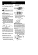
To attach blower tube:
1. Align the grooves on the blower tube
with the grooves on the blower outlet.
2. Push the blowertube onto the blower
outlet until it snap s into place (tube is
secured by red tube release button).
3. To remove the blower tube, press the
tube release button while pulling on
tube.
Blower Tube
Blower outlet
Tube Release Button
VACUUM ASSEMBLY
NOTE: Assembly instructions for using
your unit as a blower are explained in the
previous sec tion.
If you have alr ea dy assembled your unit
for use as a blower, remove t he bl ow er
tube.
Remove the inlet restrictor
An inlet restrictor is used when using your
unit as a blower. This restri ct or is not used
during vacuum use and must be removed
during assembl y for vacuum use.
NOTE: Be sure to keep the inlet re-
strictor for using your unit as a blower.
1. Ensure unit is stopped and extension
cord is unplugged.
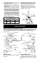
2. Open the inlet cover by inserting the
tip of a screwdriverinto the latch area
on the blower u nit. Gently tilt hand le
of screwdriver toward the front of the
unit to release the latch while pulling
up on the vacu um inlet cover with
your other hand.
Vacuum Inlet Cover (closed)
Latch Area
Bottom view
of unit
Vacuum Inlet Cover (opened)
Latch Area
Impeller
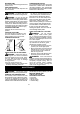
3. Turn the inlet restrictor counterclock-
wise and remove it f rom the unit. Do
not close the inlet door. You will next
att ach the vacuum tubes.
Inlet
Restrictor
Vacuum
Inlet Cover
Attaching the vacuum tubes
There are 2 vacuum tubes, an upper
tube and a lower tube. The upper tube
has a vacuum assist handle attached to
one end and is cut straighton both ends .
The upper tube attaches to the blower
unit. The lower tube has an angled end
that yo u point toward the ground during
vacuum use. The lower tube attaches to
the upper tube.
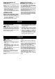
1. Ensure unit is stopped an d exten-
sion cord is unplugged.
2. While holding inlet cover open, place
th e hooks of the va cuum assist handle
on the retai n ing posts of the unit.
3. Raise the tube until it is secured to the
blower unit by the red inlet cover lat ch.
Retaining Post
Vacuum Assist Handle
Upper
V
acuum Tube
Hook