Model No. 831.14922.0 Serial No. Write the serial number in the space above for reference. Serial Number Decal (under the seat) • Assembly • Operation • Maintenance • Part List and Drawing Sears, Roebuck and Co. Hoffman Estates, IL 60179 CAUTION Read all precautions and instructions in this manual before using this equipment. Keep this manual for future reference.
TABLE OF CONTENTS WARNING DECAL PLACEMENT . . . . . . . . . . . . . . . . . . . . . . . . . . . . . . . . . . . . . . . . . . . . . . . . . . . . . . . . . . . . . .2 IMPORTANT PRECAUTIONS . . . . . . . . . . . . . . . . . . . . . . . . . . . . . . . . . . . . . . . . . . . . . . . . . . . . . . . . . . . . . . . .3 BEFORE YOU BEGIN . . . . . . . . . . . . . . . . . . . . . . . . . . . . . . . . . . . . . . . . . . . . . . . . . . . . . . . . . . . . . . . . . . . . . .4 PART IDENTIFICATION CHART . . . . .
IMPORTANT PRECAUTIONS WARNING: To reduce the risk of serious injury, read all important precautions and instructions in this manual and all warnings on your weight system before using your weight system. Sears assumes no responsibility for personal injury or property damage sustained by or through the use of this product. 1. Before beginning any exercise program, consult your physician. This is especially important for persons over age 35 or persons with pre-existing health problems.
BEFORE YOU BEGIN reading this manual, please see the front cover of this manual. To help us assist you, note the product model number and serial number before contacting us. The model number and the location of the serial number decal are shown on the front cover of this manual. Thank you for selecting the versatile WEIDER PRO® 6900 weight system. The weight system offers a selection of weight stations designed to develop every major muscle group of the body.
PART IDENTIFICATION CHART Refer to the drawings below to identify small parts used in assembly. The number in parentheses by each drawing is the key number of the part, from the PART LIST near the end of this manual. IMPORTANT: If you cannot find a part in the hardware kit, check to see if it has been preassembled. If a part is missing, please call 1-877-992-5999. To avoid damaging parts, do not use power tools for assembly.
ASSEMBLY To make assembly easier, carefully read the following information and instructions: • The following tools (not included) may be required for assembly: two adjustable wrenches • Assembly requires two persons. one rubber mallet • Because of its weight and size, assemble the weight system in the location where it will be used. Make sure that there is enough clearance to walk around the weight system.
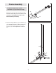
1. Frame Assembly 1 To make assembly easier, read the information on page 6 before you begin. Attach the Foot Plate (38) to the Base (1) with an M10 x 130mm Bolt (72) and an M10 Locknut (56). Do not overtighten the Locknut; the Foot Plate must pivot easily. 2. Attach the Weight Guides (21) and the Base (1) to the Stabilizer (2) with two M10 x 67mm Bolts (71), two M10 Washers (57), and two M10 Locknuts (56). Do not tighten the Locknuts yet.
3. Attach the Upright (3) to the Base (1) with two M8 x 63mm Carriage Bolts (87) and two M8 Locknuts (58). Do not tighten the Locknuts yet. 3 3 58 58 1 87 4. Attach the Front Leg (7) to the Base (1) with two M8 x 63mm Carriage Bolts (87) and two M8 Locknuts (58). Do not tighten the Locknuts yet.
5. Attach the Seat Tube (6) to the Upright (3) with two M8 x 65mm Bolts (68), two M8 Washers (59), and two M8 Locknuts (58). Do not tighten the Locknuts yet. 5 Attach the Seat Tube (6) to the Front Leg (7) in the same way. 68 7 58 6. Slide the two Weight Bumpers (27) onto the Weight Guides (21). Orient nine Weights (22) so that the pin holes are on the bottom as shown. Slide the Weights onto the Weight Guides (21).
7. Attach the Top Frame (4) to the Upright (3) with two M10 x 67mm Bolts (71), two M10 Washers (57), and two M10 Locknuts (56). Do not tighten the Locknuts yet. 7 Attach the Top Frame (4) to the Weight Guides (21) with two M10 x 25mm Bolts (74). Do not tighten the Bolts yet. 4 See steps 2 to 7. Tighten the M10 Locknuts (56) and the M8 Locknuts (58). 57 74 71 56 56 3 8. Attach the Leg Bumper (60) to the Front Leg (7) with an M4 x 20mm Self-tapping Screw (69) and an M4 Washer (33).
10. Apply grease to an M10 x 77mm Bolt (79). Attach the Pivot Frame (5) to the Top Frame (4) with the M10 x 77mm Bolt (79) and an M10 Locknut (56). Do not overtighten the Locknut; the Pivot Frame must pivot easily. Arm Assembly 10 4 56 5 Grease 79 11 11. Attach the two Arm Pins (40) to the Pivot Frame (5) with two M4 x 20mm Self-tapping Screws (69). 69 See the inset drawing. Insert the Arm Pins (40) into the indicated holes in the Upright (3). 5 40 69 40 12.
13. Apply grease to an M10 x 86mm Carriage Bolt (67) and to two Arm Bushings (44). Attach the Left Arm (10) to the Pivot Frame (5) with the M10 x 86mm Carriage Bolt (67), a Carriage Bolt Bushing (20), the two Arm Bushings (44), an M10 Washer (57), and an M10 Locknut (56). Do not overtighten the Locknut; the Left Arm must pivot easily. 13 9 Attach the Right Arm (9) to the Pivot Frame (5) in the same way. 67 5 20 57 56 Grease Cable Assembly Grease 44 44 10 14 14.
15. Identify the two V-pulleys (46), the nine Thick Pulleys (not shown), and the two Thin Pulleys (not shown). 15 Route the Arm Cable (54) over a V-pulley (46). Attach the V-pulley (46), a Large Cable Trap (50), two Full Guards (41), and an M10 Washer (57) to the Upright (3) with an M10 x 63mm Bolt (75) and an M10 Locknut (56). 3 Make sure that the Large Cable Trap (50) is oriented to hold the Arm Cable (54) in the groove of the V-pulley (46). 16. Route the Arm Cable (54) around a Thick Pulley (48).
18. Apply grease to an M8 x 22mm Shoulder Bolt (65). Attach the Arm Cable (54) to the right Cable Pivot (39) with the M8 x 22mm Shoulder Bolt (65) and an M8 Locknut (58). 19. Identify the Low Cable (53). Route the Low Cable through the Leg Lever (8) and the Front Leg (7). 18 Grease 19 56 57 Attach a Thick Pulley (48) inside the Leg Lever (8), above the Low Cable (53), with an M10 x 67mm Bolt (71), two M10 Washers (57), two 13mm Spacers (52), and an M10 Locknut (56). 20.
21. Route the Low Cable (53) through the Upright (3) and under a Thick Pulley (48). Attach the Thick Pulley (48) inside the Upright (3) with an M10 x 46mm Bolt (81) and an M10 Locknut (56). 22. Route the Low Cable (53) over a Thick Pulley (48). Attach the Thick Pulley (48) and two Half Guards (43) to the Double U-bracket (63) with an M10 x 46mm Bolt (81) and an M10 Locknut (56). Make sure that the Half Guards are on the outside of the Double U-bracket as shown. 23.
24. Attach the Low Cable (53) to the U-bracket (45) with an M8 Washer (59) and an M8 Locknut (58). 24 58 See the inset drawing. Do not overtighten the M8 Locknut (58); it should be threaded onto the end of the Low Cable (53) so that only two threads are showing above the Locknut. 59 45 53 45 58 53 25. Identify the High Cable (55). Route the High Cable upward through the Top Frame (4) and over a Thick Pulley (48).
27. Wrap the High Cable (55) under a Thick Pulley (48). Attach the Thick Pulley (48), a Small Cable Trap (51), and two Half Guards (43) to the upper hole in the U-bracket (45) with an M10 x 51mm Bolt (66) and an M10 Locknut (56). 27 56 43 Make sure that the Small Cable Trap (51) is oriented to hold the High Cable (55) in the groove of the Thick Pulley (48) and that the Half Guards (43) are on the outside of the Ubracket (45). 28.
30. Thread an M12 Nut (84) all the way onto the High Cable (55). Place a Large Washer (85) on top of the Weight Selector (24). 30 55 84 85 Tighten the High Cable (55) into the Weight Selector (24) until all the slack is removed from the cables. Tighten the M12 Nut (84) against the Large Washer (85). Seat Assembly 31 31. Attach the Backrest (16) to the Backrest Frame (61) with two M6 x 16mm Screws (62), an M6 x 32mm Screw (64), and an M6 Washer (82).
33. Insert the Pad Tube (29) into the Front Leg (7). Slide a Small Foam Pad (28) onto each side of the Pad Tube (29). Then, press a Pad Cap (34) into each Small Foam Pad. 33 28 34 34 Slide a Small Foam Pad (28) onto each end of the Leg Lever (8). Then, press a Pad Cap (34) into each Small Foam Pad. 28 7 29 8 28 28 34. Attach a Shroud Support (19) and the top of the Left Shroud (17) to the left side of the Top Frame (4) with two M4.2 x 16mm Self-tapping Screws (49) and two M4 Washers (33).
35. Attach a Shroud Support (19) and the bottom of the Left Shroud (17) to the Base (1) and the Stabilizer (2) with four M4.2 x 16mm Self-tapping Screws (49) and four M4 Washers (33). Do not tighten the Screws yet. 35 17 Repeat steps 34 and 35 to attach the Right Shroud (not shown). See steps 34 and 35. Tighten the M4.2 x 16mm Self-tapping Screws (49) and the M4 x 12mm Screws (78). 1 49 36. Attach the Curl Pad (14) to the Curl Post (13) with two M6 x 16mm Screws (62).
ADJUSTMENT This section explains how to adjust the weight system. See the EXERCISE GUIDELINES on page 26 for important information about how to get the most benefit from your exercise program. Also, refer to the accompanying exercise guide to see the correct form for several exercises. Make sure that all parts are properly tightened each time the weight system is used. Replace any worn parts immediately.
CONVERTING THE ARMS To use the Arms (9, 10) as butterfly arms, insert the Arm Pins (40) into the holes in the Upright (3) as shown. 9 To use the Arms (9, 10) as press arms, insert the Arm Pins (40) into the holes in the Pivot Frame (5) and the Arms. 40 Holes 5 CONVERTING THE FOOT PLATE To use the Foot Plate (38) as a footrest while using the low pulley station, rotate the Foot Plate upward.
LOCKING THE WEIGHT STACK 21 To lock the weight stack after each workout, insert the Lock Pin (89) through one of the Weight Guides (21), and secure the Lock (88) on the Lock Pin. 88 89 WEIGHT RESISTANCE CHART The chart below shows the approximate weight resistance at each exercise station. The numbers in the left column refer to the 12.5-lb. weights. Note: The weight resistance shown for the butterfly arm station is for each arm.
CABLE DIAGRAM The drawings below shows the proper routing of the cables. The numbers in each drawing show the proper route of that cable. Use the drawings to make sure that the cables, cable traps, and guards are assembled correctly. If the cables are not assembled correctly, the weight system will not function properly and damage may occur. Make sure that the cable traps do not touch or bind the cables. High Cable (55) Length: 126 in. (320 cm) 4 Arm Cable (54) Length: 101 in.
MAINTENANCE Make sure that all parts are properly tightened each time the weight system is used. Replace any worn parts immediately. To clean the weight system, use a damp cloth and a mild, non-abrasive detergent; do not use solvents to clean the weight system. TIGHTENING THE CABLES Woven cable, the type of cable used on the weight system, can stretch slightly when it is first used. If there is slack in the cables before resistance is felt, the cables should be tightened.
EXERCISE GUIDELINES FOUR TYPES OF STRENGTH WORKOUTS Note: A “repetition” is one complete cycle of an exercise, such as one sit-up. A “set” is a series of repetitions. Muscle Building—Work your muscles near their maximum capacity and progressively increase the intensity of your exercise. Adjust the intensity level of an individual exercise as follows: • Change the amount of resistance used. • Change the number of repetitions or sets performed.
EXERCISE LOG Make copies of this page, and use the copies to schedule and record your strength and aerobic workouts. Scheduling and recording your workouts will help you to make exercise a regular and enjoyable part of your life. Strength Date: Exercise 1. Lbs. Sets Reps 2. 8. 4. Strength Date: 9. 5. 10. Exercise Exercise 1. Time Lbs. Sets Reps 2. Strength Date: Exercise 1. 6. 9. 5. Exercise Lbs. Sets Reps Exercise 8. 4. Aerobic Date: Distance Speed 7. 3. 10. Time Lbs.
NOTES 28
PART LIST—Model No. 831.14922.0 Key No. Qty.
EXPLODED DRAWING A—Model No. 831.14922.
EXPLODED DRAWING B—Model No. 831.14922.
Get it fixed, at your home or ours! Your Home For repair—in your home—of all major brand appliances, lawn and garden equipment, or heating and cooling systems, no matter who made it, no matter who sold it! For the replacement parts, accessories, and user’s manuals that you need to do-it-yourself. For Sears professional installation of home appliances and items like garage door openers and water heaters. 1-800-4-MY-HOME® (1-800-469-4663) Call anytime, day or night (U.S.A. and Canada) www.sears.com www.