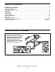
Model No. WEBE1915.0 Serial No. USER’S MANUAL Write the serial number in the space above for reference. Serial Number Decal (under seat) QUESTIONS? As a manufacturer, we are committed to providing complete customer satisfaction. If you have questions, or if parts are missing, PLEASE DO NOT CONTACT THE STORE; please contact Customer Care. IMPORTANT: You must note the product model number and serial number (see the drawing above) before contacting us: CALL TOLL-FREE: 1-877-992-5999 Mon.–Fri., 6 a.m.–6 p.
TABLE OF CONTENTS WARNING DECAL PLACEMENT . . . . . . . . . . . . . . . . . . . . . . . . . . . . . . . . . . . . . . . . . . . . . . . . . . . . . . . . . . . . . .2 IMPORTANT PRECAUTIONS . . . . . . . . . . . . . . . . . . . . . . . . . . . . . . . . . . . . . . . . . . . . . . . . . . . . . . . . . . . . . . . . 3 BEFORE YOU BEGIN . . . . . . . . . . . . . . . . . . . . . . . . . . . . . . . . . . . . . . . . . . . . . . . . . . . . . . . . . . . . . . . . . . . . . . 4 PART IDENTIFICATION CHART . . . .
IMPORTANT PRECAUTIONS WARNING: To reduce the risk of serious injury, read all important precautions and instructions in this manual and all warnings on the weight bench before using the weight bench. ICON assumes no responsibility for personal injury or property damage sustained by or through the use of the weight bench. 1. Before beginning any exercise program, consult your physician. This is especially important for persons over the age of 35 or persons with pre-existing health problems.
BEFORE YOU BEGIN Thank you for selecting the versatile WEIDER® 350 weight bench. The WEIDER 350 weight bench is designed to help develop every major muscle group of the body. Whether your goal is to tone your body, build dramatic muscle size and strength, or improve your cardiovascular system, the weight bench will help you to achieve the specific results you want. number and serial number before contacting us.
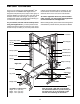
PART IDENTIFICATION CHART Refer to the drawings below to identify small parts used in assembly. The number in parentheses by each drawing is the key number of the part, from the PART LIST near the end of this manual. Note: Some small parts may have been preattached. If a part is not in the parts bag, check to see if it has been preattached.
ASSEMBLY Make Assembly Easier • Place all parts in a cleared area and remove the packing materials. Do not dispose of the packing materials until assembly is completed. Everything in this manual is designed to ensure that the weight bench can be assembled successfully by almost anyone. By setting aside plenty of time, assembly will go smoothly. • As you assemble the weight bench, make sure all parts are oriented as shown in the drawings.
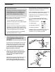
3. Attach the Olympic Adapter (22) to the Weight Tube (6) with an M8 x 10mm Set Screw (99). 3 Attach the Weight Tube (6) inside the Leg Lever (4) with an M8 x 60mm Bolt (91), two M8 Washers (84), a 13mm x 13mm Spacer (78), and an M8 Nylon Locknut (81). Next, press the 25mm Round Angled Cap (19) onto the Weight Tube; make sure the widest part of the Round Angled Cap is at the bottom. 80 3 4 85 19 81 84 78 Grease 84 22 Apply grease to an M10 x 68mm Bolt (85).
6. Insert the Backrest Bracket (7) through the indicated hole in the Bench Frame (1). 6 Apply grease to an M10 x 183mm Bolt (98). Attach the Backrest Frames (9) to the Bench Frame (1) with the Bolt, two M10 Washers (83), and an M10 Nylon Locknut (80). Do not overtighten the Nylon Locknut; the Backrest Frames must pivot easily. 9 Attach the Adjustment Pin (20) to the Bench Frame (1) with an M4 x 13mm Self-tapping Screw (94). Insert the Adjustment Pin into the Bench Frame and the Backrest Bracket (7).
10. Orient the Center Base (24) so that the indented holes are downward. Insert two M10 x 62mm Carriage Bolts (97) up through the Center Base. 10 24 85 Indented Holes Locate the Side Base (51) that has a warning decal. Orient the Side Base as shown and attach it to the Center Base (24) with two M10 x 68mm Bolts (85), two M10 Washers (83), and two M10 Nylon Locknuts (80). Do not tighten the Nylon Locknuts yet. Warning Decal 83 85 97 83 51 80 Attach the other Side Base (51) in the same way. 11 11.
13. Insert an M10 x 20mm Bolt (89) into the Weight Carriage (35). Orient the Weight Carriage and the Rear Upright (27) as shown. Slide the Weight Carriage onto the Upright. 13 Tall Side Orient the Weight Carriage Stop (48) so the 60mm Bushing (54) is at the top. Slide the Weight Carriage Stop onto the Rear Upright (27) and secure it with an M8 x 70mm Bolt (93) and an M8 Nylon Locknut (81). 27 93 81 89 35 48 14.
16. Attach a Front Upright (29) to the right Side Base (51) with two M10 x 68mm Bolts (85), four M10 Washers (83), and two M10 Nylon Locknuts (80). Do not tighten the Nylon Locknuts yet. 16 29 Repeat this step with the left Side Base (51). 80 83 83 85 51 17. Slide one of the Safety Spotters (38) onto the right Guide Rod (28). Engage the Spotter Hook (40) into one of the holes near the lower end of the right Front Upright (29). 17 36 36 37 Short End See the inset drawing.
19. Attach the Top Frame (31) to the Rear Upright (27) with two M10 x 68mm Bolts (85), four M10 Washers (83), and two M10 Nylon Locknuts (80). Do not tighten the Nylon Locknuts yet. 19 85 31 Attach the Top Frame (31) to the Center Upright (26) with two M10 x 68mm Bolts (85), two M10 Washers (83), and two M10 Nylon Locknuts (80). Do not tighten the Nylon Locknuts yet.
22. Slide an Olympic Adapter (22) onto the Barbell (42) and secure it with an M8 x 10mm Set Screw (99). 22 Repeat this step for the other end of the Barbell (42). 42 22 99 23. See the CABLE DIAGRAM on page 20 to identify the cables as you assemble them. 23 55 Identify the Lat Cable (74). Route the Cable up through the Top Frame (31) and over a 90mm Pulley (55).
25. Route the Lat Cable (74) under a 90mm Pulley (55). Attach the Pulley and a Cable Trap (61) to two Pulley Plates (59) with an M10 x 48mm Bolt (92), two Half Guards (58), and an M10 Nylon Locknut (80). Make sure the Cable Trap is oriented to hold the Cable in the groove of the Pulley. Do not overtighten the Nylon Locknut; the Pulley must turn freely. 25 80 61 74 55 58 58 92 59 59 26. Route the Lat Cable (74) up through the Top Frame (31), over a 90mm Pulley (55), and down through the Top Frame.
29. Wrap the Butterfly Cable (76) around a “V”-pulley (56). Attach the “V”-pulley and a Large Cable Trap (63) to the Center Upright (26) with an M10 x 62mm Bolt (88), two Guards (62), an M10 Washer (83), and an M10 Nylon Locknut (80). Make sure the Cable Trap is oriented to hold the Cable in the groove of the Pulley. Do not overtighten the Nylon Locknut; the Pulley must turn freely. 29 83 76 63 80 26 62 30. Route the Butterfly Cable (76) under a 90mm Pulley (55).
33. Identify the Low Cable (75). Route the Cable through the Center Upright (26) and under a 115mm Pulley (57). Attach the Pulley inside the Upright with an M10 x 68mm Bolt (85), two M10 Washers (83), two 16mm x 13mm Bushings (77), and an M10 Nylon Locknut (80). 33 57 83 80 77 26 77 83 85 75 34. Route the Low Cable (75) over a 90mm Pulley (55). Attach the Pulley to the Double Pulley Bracket (60) with an M10 x 48mm Bolt (92), two Half Guards (58), and an M10 Nylon Locknut (80).
37. Attach the Low Cable (75) to the Rear Base (25) with an M10 x 68mm Bolt (85), two 16mm x 22mm Spacers (82), two M10 Washers (83), and an M10 Nylon Locknut (80). 37 80 83 82 75 25 82 83 38. Attach the Rack Backrest (45) to the Center Upright (26) with two M6 x 63mm Screws (87) and two M6 Washers (96). 85 38 87 96 26 45 87 96 39. Lightly apply soapy water to the inside of a Long Foam Pad (47). Slide the Foam Pad onto the Right Butterfly Arm (34).
ADJUSTMENT This section explains how to adjust the weight bench. See the EXERCISE GUIDELINES on page 22 for important information about how to get the most benefit from your exercise program. Also, refer to the accompanying exercise guide to see the correct form for each exercise. Make sure all parts are properly tightened each time you use the weight bench. Replace any worn parts immediately. The weight bench can be cleaned with a damp cloth and a mild, non-abrasive detergent. Do not use solvents.
ATTACHING THE LAT BAR To attach the Lat Bar (68) to the Lat Cable (74), attach a Cable Clip (72) to the Lat Bar and the Lat Cable. Note: For some exercises, you will need to attach the Chain (not shown) between the Lat Bar and the Lat Cable. Attach one link of the Chain to the Lat Bar with a Cable Clip, and attach another link of the Chain to the Lat Cable with the other Cable Clip. 74 72 68 Attach the Lat Bar (68) and other accessories to the Low Cable (not shown) in the same manner.
CABLE DIAGRAM The cable diagrams below show the proper routing of the Lat Cable, the Low Cable, and the Butterfly Cable. Use the diagrams to make sure that the cables, the cable traps, and the guards have been assembled correctly. If the cables have not been correctly routed, the weight system will not function properly and damage may occur. The numbers show the correct route for each cable. Make sure that the cable traps do not touch or bind the cables. 3 Lat Cable (74) Length: 11 ft. 11 in.
MAINTENANCE Make sure all parts are properly tightened each time you use the weight system. Replace any worn parts immediately. The weight system can be cleaned with a damp cloth and a mild, non-abrasive detergent; do not use solvents. TIGHTENING THE CABLES Woven cable, the type of cable used on the weight rack, can stretch slightly when it is first used. If there is slack in the cables before resistance is felt, the cables should be tightened. See ATTACHING WEIGHTS in the ADJUSTMENT section of this manual.
EXERCISE GUIDELINES THE FOUR BASIC TYPES OF WORKOUTS Muscle Building To increase the size and strength of your muscles, push them close to their maximum capacity. Your muscles will continually adapt and grow as you progressively increase the intensity of your exercise. You can adjust the intensity level of an individual exercise in two ways: • by changing the amount of resistance used • by changing the number of repetitions or sets performed.
The repetitions in each set should be performed smoothly and without pausing. The exertion stage of each repetition should last about half as long as the return stage. Proper breathing is important. Exhale during the exertion stage of each repetition and inhale during the return stage. Never hold your breath. COOLING DOWN End each workout with 5 to 10 minutes of stretching. Include stretches for both your arms and legs. Move slowly as you stretch and do not bounce.
PART LIST—Model No. WEBE1915.0 Key No. Qty. 1 2 3 4 5 6 7 8 9 10 11 12 13 14 15 16 17 18 19 20 21 22 23 24 25 26 27 28 29 30 31 32 33 34 35 36 37 38 39 40 41 42 43 44 45 46 47 48 49 50 51 52 53 1 1 1 1 1 1 1 1 2 3 1 1 1 16 7 3 4 6 1 1 1 3 6 1 1 1 1 2 2 1 1 1 1 1 1 1 1 2 2 2 1 1 1 4 1 1 2 1 3 2 2 2 8 Description Key No. Qty.
EXPLODED DRAWING A—Model No. WEBE1915.
EXPLODED DRAWING B—Model No. WEBE1915.
EXPLODED DRAWING C—Model No. WEBE1915.
ORDERING REPLACEMENT PARTS To order replacement parts, please see the front cover of this manual. To help us assist you, be prepared to provide the following information when contacting us: • the model number and serial number of the product (see the front cover of the manual) • the name of the product (see the front cover of this manual) • the key number and description of the part(s) (see the PART LIST and the EXPLODED DRAWING near the end of this manual) LIMITED WARRANTY ICON Health & Fitness, Inc.