Model No. 831.159830 Serial No. USER’S MANUAL The serial number is found in the location shown below. Write the serial number in the space above. Serial Number Decal Patent Pending SEARS, ROEBUCK AND CO. HOFFMAN ESTATES, IL 60179 CAUTION Read all precautions and instructions in this manual before using this equipment. Save this manual for future reference. Visit our website at www.weiderfitness.
TABLE OF CONTENTS IMPORTANT PRECAUTIONS . . . . . . . . . . . . . . . . . . . . . . . . . . . . . . . . . . . . . . . . . . . . . . . . . . . . . . . . . . . . . 3 BEFORE YOU BEGIN . . . . . . . . . . . . . . . . . . . . . . . . . . . . . . . . . . . . . . . . . . . . . . . . . . . . . . . . . . . . . . . . . . . 4 ASSEMBLY . . . . . . . . . . . . . . . . . . . . . . . . . . . . . . . . . . . . . . . . . . . . . . . . . . . . . . . . . . . . . . . . . . . . . . . . . . . 5 ADJUSTMENTS . . . . . . . . . . .
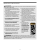
IMPORTANT PRECAUTIONS WARNING : To reduce the risk of serious injury, read the following important precautions before using the weight system. 1. Read all instructions in this manual and in the accompanying literature before using the weight system. 11. Never release the press arm, butterfly arms, leg lever, press plate, lat bar, ab strap, or nylon strap while weights are raised; the weights will fall with great force. 2.
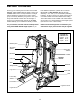
BEFORE YOU BEGIN Thank you for selecting the innovative and versatile WEIDER® PRO POWER STACK weight system. The POWER STACK offers a unique selection of weight stations designed to develop every major muscle group of the body. Whether your goal is to tone your body, build dramatic muscle size and strength, or improve your cardiovascular system, the POWER STACK will help you to achieve the results you want.
ASSEMBLY Make sure you have the following tools: Make Assembly Easier for Yourself • Two adjustable wrenches Everything in this manual is designed to ensure that the weight system can be assembled successfully by anyone. Before beginning assembly, make sure to read the information on this page. This brief introduction will save you much more time than it takes to read it.
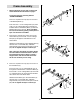
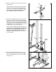
1 Frame Assembly 1. Before beginning, be sure that you have read and understood the information on page 5. 67 Locate and open the parts bag labeled “FRAME ASSEMBLY.” 1 95 Press a 2” Square Inner Cap (67) into each end of the Butterfly Base (1). 75 75 Insert four 5/16” x 2 1/2” Carriage Bolts (75) and a a 3/8” x 3 1/2” Carriage Bolt (95) up through the indicated holes in the Butterfly Base (1). Place the Butterfly Base flat on the floor.
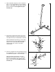
4. Slide the Butterfly Upright (4) over the indicated 5/16” x 2 1/2” Carriage Bolts (75) in the Butterfly Base (1). Hand tighten two 5/16” Nylon Locknuts (86) onto the Bolts. Do not tighten the Nylon Locknuts yet. 4 4 86 86 1 75 5. Press three 2” Square Inner Caps (67) into the Butterfly Top Frame (7). Press two Round Inner Caps (63) into the top of the Butterfly Top Frame.
ADJUSTMENTS The instructions below describe how each part of the weight system can be adjusted. Refer to the exercise guide accompanying this manual to see how the weight system should be set up for each exercise. IMPORTANT: When using an accessory, make sure it is in the correct starting position for the exercise to be performed. If there is any slack in the cables or chain as an exercise is performed, the effectiveness of the exercise will be reduced.
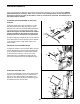
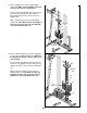
10. Press a 2” Square Inner Cap (67) into the Press Top Frame (9). 10 89 67 Attach the Press Top Frame (9) to the indicated bracket at the top of the Press Upright (5) with two 5/16” x 2 3/4” Bolts (89), a Medium Support Plate (109), and two 5/16” Nylon Locknuts (86). Do not tighten the Nylon Locknuts yet. 109 9 5 86 11. Identify the Left Weight Guides (27), which have welded rings near the bottom. Slide two Weight Bumpers (46) onto the Left Weight Guides.
13. Slide six Weights (41) onto the Right Weight Guides (26). Make sure the Weights are turned so the pin grooves are on the bottom. 13 Press a Weight Tube Bumper (45) into the lower end of the Short Weight Tube (44). Slide the Short Weight Tube into the center holes in the Weights (41). 26 42 Slide a Top Weight (42) onto the Right Weight Guides (26). Note: Make sure the Top Weight is turned so the groove fits over the welded pin on the Short Weight Tube (44). Welded Pin 44 41 45 Pin Grooves 14.
15. Press a 2” Square Inner Cap (67) into the Center Top Frame (8). Place the Center Top Frame on the indicated brackets on the Uprights (4, 5). Note: The tops of the four Weight Guides (26, 27) must be behind the Center Top Frame, as shown in step 16. 15 82 28 82 Attach the Center Top Frame (8) to the Butterfly Top Frame (7) with two 3/8” x 2 3/4” Bolts (82), a Large Support Plate (29), and two 3/8” Nylon Locknuts (90). Do not tighten the Nylon Locknuts yet.
18 Arm Assembly 92 11 67 18. Locate and open the parts bag labeled “ARM ASSEMBLY.” 104 Press two 2” Square Inner Caps (67) into the ends of the Leg Lever (13). 13 Lubricate a 3/8” x 3 1/4” Bolt (104). Attach the Leg Lever (13) to the Butterfly Leg (11) with the Bolt and a 3/8” Nylon Jamnut (92). Do not overtighten the Nylon Jamnut; the Leg Lever must be able to pivot easily. Lubricate 67 19. Lubricate the 3/8” x 3” Bolt (88).
22. Identify the Right and Left Butterfly Arms (19, 20) by the positions of the welded brackets. 22 Bracket 7 Lubricate Axles Press a 1 3/4” Square Inner Cap (68) into each end of the Right Butterfly Arm (19). Wet the lower end of the Butterfly Arm with soapy water. Slide a Large Foam Pad (53) onto the lower end of the Butterfly Arm. Welded Brackets Lubricate the axles on the Butterfly Top Frame (7). Orient the Right Butterfly Arm (19) as shown and slide it onto the right axle.
25. Remove the 3 1/2” Pulleys (35) from the Double “U”-Bracket (31). 25 Wrap the Butterfly Cable (73) around a 3 1/2” Pulley (35). Attach the Pulley to the Double “U”Bracket (31) with a 3/8” x 1 3/4” Bolt (94) and a 3/8” Nylon Locknut (90). 73 90 94 35 31 26. Remove another “V”-Pulley (34) from the bag labeled “PULLEY BAG 2.” 26 Wrap the Butterfly Cable (73) around the “V”Pulley (34) in the direction shown.
29. Remove the 3 1/2” Pulleys (35) from a pair of preassembled Pulley Plates (32). 29 Wrap the Rear Cable (70) around a 3 1/2” Pulley (35) in the direction shown. Attach the Pulley and a Cable Trap (38) to the top hole in the pair of Pulley Plates (32) with a 3/8” x 2” Bolt (93) and a 3/8” Nylon Locknut (90). Make sure the Cable Trap is positioned to hold the Cable in the groove of the Pulley. 70 93 32 30. Wrap the Rear Cable (70) around a 4 1/2” Pulley (36) in the direction shown.
33. Remove the 3 1/2” Pulleys (35) from the other pair of pre-assembled Pulley Plates (32). 33 Wrap the Ab Cable (74) around a 3 1/2” Pulley (35) in the direction shown. Attach the Pulley and a Cable Trap (38) to the top hole in the pair of Pulley Plates (32) with a 3/8” x 2” Bolt (93) and a 3/8” Nylon Locknut (90). Make sure the Cable Trap is positioned to hold the Cable in the groove of the Pulley. 74 93 90 35 32 34. Wrap the Ab Cable (74) around a 3 1/2” Pulley (35) in the direction shown.
37. Wrap the Ab Cable (74) around a 3 1/2” Pulley (35) in the direction shown. Attach the Pulley to the indicated bracket on the Center Base (2) with a 3/8” x 3 3/4” Bolt (101) and a 3/8” Nylon Locknut (90). Make sure the Cable is routed in the direction shown. 37 35 74 101 Note: The 3/8” x 3 3/4” Bolt (101) must be inserted through both brackets on the Center Frame (2). Tighten the 3/8” Nylon Locknut (90) only a few turns onto the Bolt; it will need to be removed in step 39. 90 38.
41. Locate the Weight Plate (48) that is attached to the bottom of the Bottom Weight (47). 41 86 See the inset drawing. Attach the end of the Ab Cable (74) to the bottom of the Weight Plate (48) with a 5/16” x 1 3/4” Bolt (96) and a 5/16” Nylon Locknut (86). 48 96 47 74 42. Remove a Pro Pulley (110) from the bag labeled “PULLEY BAG 2.” 42 Identify the Low Cable (71). It is approximately 142 1/8” long and it has a ball on one end and an eyelet on the other.
45. Remove the 3/8” Nylon Jamnut (92) from the 3/8” x 4 3/4” Bolt (102) inserted into the Butterfly Upright (4) in step 43. 45 71 Wrap the Low Cable (71) around a 3 1/2” Pulley (35) in the direction shown. Attach the Pulley and a Cable Trap (38) to the 3/8” x 4 3/4” Bolt (102) with the 3/8” Nylon Jamnut (92). Make sure the Cable Trap is positioned to hold the Cable in the groove of the Pulley. 4 102 46.
49. Wrap the Press Cable (72) around a 3 1/2” Pulley (35) in the direction shown. Attach the Pulley and a Cable Trap (38) to the indicated hole in the Press Upright (5) with a 3/8” x 3 3/4” Bolt (101), a 3/8” Washer (97) and a 3/8” Nylon Locknut (90). Make sure the Cable Trap is positioned to hold the Cable in the groove of the Pulley. 49 90 97 35 101 38 5 50. Route the Press Cable (72) through the opening in the Press Frame (17) and wrap the Cable around a 3 1/2” Pulley (35) in the direction shown.
53. Wrap the Press Cable (72) around a 3 1/2” Pulley (35) in the direction shown. Attach the Pulley and a Cable Trap (38) to the indicated hole on the right side of the Press Upright (5) with a 3/8” x 4 3/4” Bolt (102) and a 3/8” Nylon Jamnut (92). Note: Thread the Jamnut only two turns onto the Bolt; another Pulley will be attached to the Bolt in step 57. Make sure the Cable Trap is positioned to hold the Cable in the groove of the Pulley. 53 102 72 92 5 35 38 54.
57. Remove the 3/8” Nylon Jamnut (92) used in step 53. Route the Press Cable (72) through the Press Frame (17). 57 Wrap the Press Cable (72) around a 3 1/2” Pulley (35) in the direction shown. Slide a Cable Trap (38) and the Pulley onto the 3/8” x 4 3/4” Bolt (102) in the bottom of the Press Upright (5). Properly tighten the 3/8” Nylon Jamnut (92) onto the Bolt. Make sure the Cable Trap is positioned to hold the Cable in the groove of the Pulley. 38 72 5 102 35 17 58.
61. Attach the Press Cable (72) to the remaining “U”Bracket (33) with a 1/4” Washer (99) and a 1/4” Nylon Locknut (103). Note: Do not completely tighten the Nylon Locknut; it should be threaded only two turns onto the end of the Cable, as shown in the inset drawing. 61 72 96 33 86 99 103 43 Attach the “U”-Bracket (33) to the Long Weight Tube (43) with a 5/16” x 1 3/4” Bolt (96) and a 5/16” Nylon Locknut (86).
65. Press a 1 3/4” Square Inner Cap (68) into the indicated end of the Adjustment Tube (15). 65 Attach the Adjustment Tube (15) to the bracket (not visible in the drawing) on the back of the Leg Press Plate (16) with a 5/16” x 2 1/2” Bolt (87), two 5/16” Washers (100), and a 5/16” Nylon Locknut (86). 87 Lip 40 100 15 68 14 100 86 Place the Adjustment Tube (15) in the bracket on top of the Leg Press Lever (14) and secure it with the Adjustment Pin (40).
7. Slide the Butterfly Leg (11) onto the two 5/16” x 2 1/2” Carriage Bolts (75) in the Butterfly Base (1). Hand tighten two 5/16” Nylon Locknuts (86) onto the Bolts. 7 86 89 10 86 Attach the Butterfly Seat Frame (10) to the Butterfly Upright (4) with two 5/16” x 2 3/4” Bolts (89), two 5/16” Washers (100), and two 5/16” Nylon Locknuts (86). 100 11 4 86 86 Do not tighten the 5/16” Nylon Locknuts (86) yet. 75 8. Press a 1” Square Inner Cap (69) into the small tube on the Press Upright (5).
CHANGING THE WEIGHT SETTING 41 To change the setting of a weight stack, insert a Weight Pin (81) under the desired Weight (41). Insert the Weight Pin so that the bent end touches the weight stack. Turn the bent end down. To use the Bottom Weight (47) with the press arms or the leg press, insert the Weight Pin (81) under the Bottom Weight. Remove the other Weight Pin from the small weight stack.
WEIGHT RESISTANCE CHART The chart below shows the approximate weight resistance at each exercise station. “Left Top” and “Right Top” refer to the 6 lb. top weights. “Bottom” refers to the 12.5 lb. bottom weight. The other numbers refer to the 12.5 lb. weight plates. Weight resistance shown for the butterfly arm station is for each butterfly arm.
TROUBLESHOOTING AND MAINTENANCE Make sure all parts are properly tightened each time you use the weight system. Replace any worn parts immediately. The weight system can be cleaned using a damp cloth and mild non-abrasive detergent. Do not use solvents. TIGHTENING THE CABLES Woven cable, the type of cable used on the weight system, can stretch slightly when it is first used. If there is slack in the cables before resistance is felt, the cables should be tightened.
Slack can be removed from the Press Cable (72) by moving the “V”-Pulley (34) attached to the Press Seat Frame (12) closer to the Press Upright (5). 85 Remove the 3/8” x 4 1/4” Bolt (85), 3/8” Washer (97), and 3/8” Nylon Locknut (90) from the Press Seat Frame (12), the “V”-Pulley (34), and the Long Cable Trap (37). Move the Pulley to a hole that is closer to the Press Upright (5), one hole at a time, until the slack is removed.
CABLE DIAGRAMS The Cable Diagrams below and on the next page show the proper routing of the Rear Cable (70), the Low Cable (71), the Press Cable (72), the Butterfly Cable (73), and the Ab Cable (74). The numbers show the correct route for each Cable. Make sure that the Cables are routed correctly, that the Pulleys move smoothly, and that the Cable Traps do not touch or bind the Cables. Incorrect cable routing can damage the weight system.
Ab Cable (74) Low Cable (71) 3 7 1 4 2 5 3 6 2 1 5 4 6 8 9 10 Rear Cable (70) 11 1 3 Butterfly Cable (73) 2 5 4 2 1 3 4 31
The model number and serial number of your WEIDER® PRO POWER STACK weight system are listed on a decal attached to the frame. See the front cover of this manual to find the location of the decal. Model No. 831.159830 QUESTIONS? If you find that: • you need help assembling or operating the WEIDER® PRO POWER STACK weight system All replacement parts are available for immediate purchase or special order when you visit your nearest SEARS Service Center.
This chart is provided to help you identify the small parts used in assembly. The number in parenthesis below each part refers to the key number of the part from the PART LIST in the center of this manual. Important: Some parts may have been pre-assembled for shipping purposes. If you cannot find a part in the parts bags, check to see if it has been pre-assembled. Note: Assembly is divided into four stages: 1) frame assembly; 2) arm assembly; 3) cable assembly; and 4) seat assembly.
3/4" Round Inner Cap (64) Round Inner Cap (63) 1” Retainer (54) 1" Square Inner Cap (69) 1 3/4" Square Inner Cap (68) 1" Cover Cap (55) 1" Round Inner Cap (66) 2" Square Inner Cap (67)
PART IDENTIFICATION CHART—Model No. 831.
5/16" x 1 3/4" Bolt (96) 5/16" x 1" Shoulder Bolt (84) 5/16" x 3" Bolt (107) 5/16" x 2 3/4" Shoulder Bolt (108) 1” Tap Screw (80) 3/8" x 3" Bolt (88) 3/8" x 3 1/4" Bolt (104) 3/8" x 3 1/2" Bolt (111) 3/8" x 3 1/2" Carriage Bolt (95) 3/8" x 3 3/4" Bolt (101) 3/8" x 4" Bolt (78) 3/8" x 4" Carriage Bolt (112) 3/8" x 4 1/4" Bolt (85) 3/8" x 4 3/4" Bolt (102) 3/8" x 8" Bolt (106) 1/4" x 3/4" Bolt (98)
REMOVE THIS PART LIST/EXPLODED DRAWING FROM THE MANUAL.
PART LIST—Model No. 831.159830 Key No. Qty.
64 68 52 84 73 92 64 65 51 67 71 93 67 52 13 29 77 68 67 63 7 77 100 53 19 55 54 67 82 89 52 71 50 110 38 64 73 75 86 22 89 90 1 86 11 49 84 67 67 100 77 67 63 109 86 108 80 104 68 51 20 55 54 65 53 89 86 93 35 52 79 38 75 109 86 99 99 98 23 10 56 95 90 92 64 103 86 30 91 57 83 90 35 31 90 35 35 38 58 86 94 35 82 86 97 90 35 82 90 95 97 97 67 33 35 86 92 38 35 92 45 2 86 67 97 35 67 94 1