
User's Manual

1. Before beginning, be sure that you have read
and understood the information on page 5.
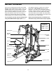
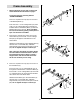
Locate and open the parts bag labeled
“FRAME ASSEMBLY.”
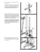
Press a 2” Square Inner Cap (67) into each end
of the Butterfly Base (1).
Insert four 5/16” x 2 1/2” Carriage Bolts (75) and a
a 3/8” x 3 1/2” Carriage Bolt (95) up through the
indicated holes in the Butterfly Base (1). Place the
Butterfly Base flat on the floor. Note: If the Bolts
fall out, secure them by putting a small piece of
tape over the head of each Bolt.
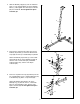
2. Press three 2” Square Inner Caps (67) into the
Center Base (2). Insert a 3/8” x 3 1/2” Carriage
Bolt (95) up through the indicated hole in the
Center Base.
Attach the Center Base (2) to the Butterfly Base (1)
with two 5/16” x 2 3/4” Bolts (89), a Medium
Support Plate (109), and two 5/16” Nylon Locknuts
(86). Do not tighten the Nylon Locknuts yet.
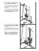
Note: There are three kinds of Support Plates.
The main difference between them is the dis-
tance between the holes. When you need a
Support Plate, find the kind with holes that
will fit over the bolts you are using.
1
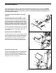
3. Press a 2” Square Inner Cap (67) into the end of
the Press Base (3).
Insert four 5/16” x 2 1/2” Carriage Bolts (75) up
through the indicated holes in the Press Base (3).
Insert a 3/8” x 2 1/2” Carriage Bolt (76) and a 3/8”
x 4” Carriage Bolt (112) up through the indicated
holes at the end of the Press Base.
Attach the Press Base (3) to the Center Base (2)
with two 5/16” x 2 3/4” Bolts (89), a Medium
Support Plate (109), and two 5/16” Nylon Locknuts
(86). Do not tighten the Nylon Locknuts yet.
3
6
Frame Assembly
75
1
67
75
67
95
75
75
76
3
2
86
67
109
89
2
95
86
112
2
67
1
89
86
109
86