¨ Model No. WESY85101 Serial No. (Write the serial number in the space above for reference.) Serial Number Decal QUESTIONS? As a manufacturer, we are committed to providing complete customer satisfaction. If you have questions, or find there are missing or damaged parts, we will guarantee you complete satisfaction through direct assistance from our factory. TO AVOID UNNECESSARY DELAYS, PLEASE CALL DIRECT TO OUR TOLL-FREE CUSTOMER HOT LINE.
TABLE OF CONTENTS LIMITED WARRANTY . . . . . . . . . . . . . . . . . . . . . . . . . . . . . . . . . . . . . . . . . . . . . . . . . . . . . . . . . . . . . . . . . . .2 IMPORTANT PRECAUTIONS . . . . . . . . . . . . . . . . . . . . . . . . . . . . . . . . . . . . . . . . . . . . . . . . . . . . . . . . . . . . .3 BEFORE YOU BEGIN . . . . . . . . . . . . . . . . . . . . . . . . . . . . . . . . . . . . . . . . . . . . . . . . . . . . . . . . . . . . . . . . . . .4 ASSEMBLY . . . . . . . . . . . . . . . . . .
IMPORTANT PRECAUTIONS WARNING: To reduce the risk of serious injury, read the following important precautions before using the home gym system. 8. Keep hands and feet away from moving parts. 1. It is the responsibility of the owner to ensure that all users of the home gym system are adequately informed of all precautions. 9. Always stand on a foot plate when performing an exercise that could cause the home gym system to tip. 2.
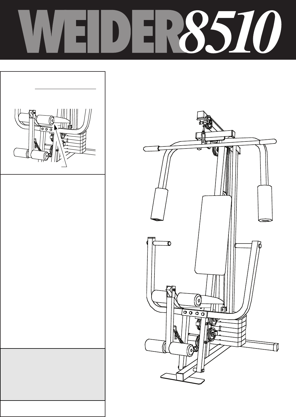
BEFORE YOU BEGIN Thank you for selecting the versatile WEIDER¨ 8510 Home Gym System. The WEIDER¨ 8510 offers a selection of weight stations designed to develop every major muscle group of the body. Whether your goal is to tone your body, build dramatic muscle size and strength, or improve your cardiovascular system, the WEIDER¨ 8510 will help you to achieve the specific results you want. Service Department toll-free at 1-800-225-0653, Monday through Friday, 6 a.m. until 6 p.m.
ASSEMBLY ¥ As you assemble the home gym system, be sure that all parts are oriented as shown in the drawings. Before beginning assembly, carefully read the following information and instructions: ¥ Place all parts of the home gym system in a cleared area and remove the packing materials; do not dispose of the packing materials until assembly is completed. ¥ Tighten all parts as you assemble them, unless instructed to do otherwise.
2. Slide the Front Upright (42) onto the 5/16Ó x 2 1/2Ó Carriage Bolts (1) in the Base (4). Hand tighten a 5/16Ó Nylon Locknut (3) onto each Carriage Bolt. Do not tighten the Nylon Locknuts yet. 2 Press a 1Ó Square Inner Cap (65) into the Front Upright (42). 42 65 FRAME ASSEMBLY 3 4 1 3. Press a 2Ó Square Inner Cap (27) into each end of the Top Frame (55). Press a 1 3/4Ó Square Inner Cap (44) into each end of the crossbar on the Top Frame.
5. Press the Weight Tube Bumper (64) into the end of the Weight Tube (63). Insert the Weight Tube into the stack of Weights (25). Be sure that the pins on the Weight Tube are resting in the pin grooves in the upper Weight. 5 Holes Lubricate the insides of the holes in the Top Weight (76). Set the Top Weight onto the stack of Weights (25). 62 Insert both Weight Guides (62) into the stack of Weights (25). Be sure that the holes in the Weight Guides are at the top, as shown.
. Press a 1 3/4Ó Square Inner Cap (44) into the top of a Press Arm (46). Press a 1Ó Round Inner Cap (49) into each end of the handle on the Press Arm. Attach the Press Arm to one side of the Press Frame (17) with two 5/16Ó x 2 1/2Ó Bolts (22) and two 5/16Ó Nylon Locknuts (3). 8 44 49 44 49 46 49 46 Assemble the other Press Arm (46) in the same manner. 22 3 17 9. Identify the Right Arm (48) and the Left Arm (47). Note the position of the welded bracket on each Arm.
11. During steps 11 through 25, refer to the CABLE DIAGRAM on page 20 of this manual to verify proper cable routing. Before beginning this section, identify the Long Cable (23) and the Short Cable (58) by comparing the lengths and ends of the cables. 11 23 IMPORTANT: While assembling the cables, do not overtighten the bolts and nuts securing the pulleys. The pulleys must be able to turn freely. CABLE ASSEMBLY 12. Locate the Long Cable (23).
15. Route the Long Cable (23) around the ÒVÓPulley (6) on the Right Arm (48). Be sure that the Cable is in the groove of the ÒVÓPulley and that the Long Cable Trap (50) is turned to hold the Cable in place. Tighten the 3/8Ó x 2 1/2Ó Bolt (7) and the 3/8Ó Nylon Locknut (not shown). 15 50 7 6 48 23 CABLE ASSEMBLY 16. Route the Long Cable (23) around the 3 1/2Ó Pulley (15) attached to the Pulley Bracket (20).
19. Note: This assembly step shows how to complete the assembly of several preattached parts. 19 The 5/8Ó x 9/16Ó Spacer (73) has been preattached on the outside of the 3 1/2Ó Low Pulley (77) for shipping purposes. Remove the 3/8Ó Nylon Locknut (21), the Spacer, and the Pulley from the 3/8Ó x 3 3/4Ó Bolt (71). Do not remove the Bolt. The Bolt has been shown removed for part identification. Reattach the 3 1/2Ó Low Pulley (77), with the 5/8Ó x 9/16Ó Spacer (73) between the Pulley and the Press Frame (17).
21. Route the Short Cable (58) around the 3 1/2Ó Pulley (15) attached to the lower hole in the Front Upright (42). See the inset drawing. Be sure that the Cable Trap (66) is turned to hold the Cable in place and that the Cable is routed around the Pulley as shown. Tighten the 3/8Ó Nylon Locknut (21) and the 3/8Ó x 3 3/4Ó Bolt (71). 21 42 15 42 71 15 66 58 Inset shows view from other side 21 22 CABLE ASSEMBLY 22.
24. Attach the end of the Short Cable (58) to the Long ÒUÓ-Bracket (57) with a 1/4Ó Nylon Locknut (2) and a 1/4Ó Flat Washer (10). Do not completely tighten the Nylon Locknut. It should be threaded onto the end of the Cable so only a couple of threads are showing above the nut, as shown in the inset drawing. 24 2 57 10 58 CABLE ASSEMBLY 2 10 57 25. Attach the Long Cable (23) to the Small ÒUÓBracket (67) with a 1/4Ó Nylon Locknut (2) and a 1/4Ó Flat Washer (10).
26. Attach the Backrest (41) to the Front Upright (42) with two 1/4Ó x 2 1/2Ó Screws (43) and two 1/4Ó Flat Washers (10). 26 42 41 SEAT ASSEMBLY 43 10 27. Press a 1 1/2Ó Square Inner Cap (32) into the Seat Frame (36). Insert the 1/4Ó x 2Ó Carriage Bolt (38) into the center hole in the Seat Plate (37). Attach the Seat Plate to the Seat (13) with two 1/4Ó x 1/2Ó Screws (18). 27 13 Insert the 1/4Ó x 2Ó Carriage Bolt (38) into the indicated hole in the Seat Frame (36).
29. Rest the Seat Frame (36) on the indicated pin in the Front Upright (42). Attach the Seat Frame to the Front Upright with a 5/16Ó x 2 3/4Ó Carriage Bolt (14) and the Seat Knob (40). 29 40 36 14 Pin SEAT ASSEMBLY 42 30. Press 3/4Ó Round Inner Caps (34) into the ends of both 12 1/2Ó Pad Tubes (28). 30 Insert one 12 1/2Ó Pad Tube (28) into the Seat Frame (36). Slide a 5 1/2Ó Pad (30) onto each end of the Pad Tube. Insert the other 12 1/2Ó Pad Tube (28) into the Leg Lever (29).
31. Remove the decals from the decal sheet (not shown) and apply them to the home gym system in the locations shown below. 31 HIGH PULLEY BUTTERFLY 8510 BENCH PRESS LEG EXTENSION LEG CURL LOW PULLEY 32. Make sure that all parts have been properly tightened. The use of the remaining parts will be explained in ADJUSTMENT, beginning on page 17 of this manual. Before using the home gym system, pull each cable a few times to be sure that the cables move smoothly over the pulleys.
ADJUSTMENT The instructions below describe how each part of the home gym system can be adjusted. Refer to the exercise poster accompanying this manual to see how the home gym system should be set up for each exercise. IMPORTANT: When attaching the lat bar or nylon strap, make sure that the attachments are in the correct starting position for the exercise to be performed. If there is any slack in the cables or chain as an exercise is performed, the effectiveness of the exercise will be reduced.
ATTACHING AND REMOVING THE SEAT Set the bracket on the Seat Frame (36) onto the indicated pins on the Front Upright (42). Attach the Seat Frame to the Front Upright with the 5/16Ó x 2 3/4Ó Carriage Bolt (14) and the Seat Knob (40). 40 36 13 42 For some exercises, the Seat (13) must be removed. First, be sure that the chain is not attached to the leg lever. Next, remove the Seat Knob (40) and the 5/16Ó x 2 3/4Ó Carriage Bolt (14) from the Seat Frame (36). Lift the Seat Frame off the Front Upright (42).
TROUBLE-SHOOTING AND MAINTENANCE Inspect and tighten all parts each time you use the home gym system. Replace any worn parts immediately. The home gym system can be cleaned using a damp cloth and mild non-abrasive detergent. Do not use solvents. TIGHTENING THE CABLES 1 Woven cable, the type of cable used on the home gym system, can stretch slightly when it is first used. If there is slack in the cables before resistance is felt, the cables should be tightened.
CABLE DIAGRAM The cable diagram below shows the proper routing of the Short Cable (58) and the Long Cable (23). Use the diagram to be sure that the two cables and the cable traps have been assembled correctly. If the cables have not been correctly routed, the home gym system will not function properly and damage may occur. The numbers show the correct route for each cable. The starting and ending points of each cable are labeled. Be sure that the cable traps do not touch or bind the cables.
NOTES 21
PART LISTÑModel No. WESY85101 Key No. Qty. 1 2 3 4 5 6 7 8 9 10 11 12 13 14 15 16 17 18 19 20 21 22 23 24 25 26 27 28 29 30 31 32 33 34 35 36 37 38 39 40 2 3 17 1 1 3 3 5 4 6 4 3 1 3 7 1 1 2 2 1 12 4 1 1 6 1 3 2 1 4 2 2 1 4 1 1 1 1 1 1 Description R1196A Key No. Qty.
EXPLODED DRAWINGÑModel No.
3/4Ó Round Inner Cap (34)Ð4 1Ó Round Inner Cap (49)Ð6 1Ó Round Cover Cap (70)Ð2 5/8Ó x 9/16Ó Spacer (73)Ð1 1/2Ó x 3/4Ó Spacer (61)Ñ2 5/16Ó x 2Ó Eyebolt (35)Ñ1 1 3/4Ó Square Inner Cap (44)Ð6 1 1/2Ó Square Inner Cap (32)Ñ2 2Ó Square Inner Cap (27)Ð3 2Ó Square Outer Cap (51)Ð2
1 1/8" x 2 1/2" Plastic Bushing (74)Ð2 1" Retainer (69)Ð4 ?? @@@@@@@@e?? N@h? ?@h?? ? @?f? @?f? @?f? @?f? @?f? @?f? ?W2@@@@6X?? W.M?e?I/X? .YgV/?? W2@@@@6Xe? 7
1/4" Nylon Locknut (2)Ð3 1/4" x 2" Screw (24)Ð1 5/16" Nylon Locknut(3)Ð17 1/4" x 2 1/2" Screw (43)Ð2 3/8" Nylon Locknut (21)Ð12 5/16" x 1 3/4" Bolt (72)Ð1 1/4" Flat Washer (10)Ð6 5/16" x 2 1/2" Bolt (22)Ð4 5/16" Flat Washer (8)Ð5 5/16" x 2 3/4" Bolt (11)Ð4 3/8" Flat Washer (9)Ð4 5/16" x 2 1/2" Carriage Bolt (1)Ð2 1/4" x 1/2" Screw (18)Ð2 5/16" x 2 3/4" Carriage Bolt (14)Ð3 1/4" x 2" Carriage Bolt (38)Ð1 5/16" x 5" Bolt (68)Ð1 5/16" x 6" Bolt (60)Ð1
ORDERING REPLACEMENT PARTS To order replacement parts, simply call our Customer Service Department toll-free at 1-800-225-0653, Monday through Friday, 6 a.m. until 6 p.m. Mountain Time (excluding holidays). To help us assist you, please be prepared to give the following information: 1. The MODEL NUMBER of the product (WESY85101). 2. The NAME of the product (WEIDER¨ 8510 Home Gym System). 3. The SERIAL NUMBER of the product (see the front cover of this manual). 4.