Model No. WEBE3777.0 Serial No. Write the serial number in the space above for future reference. USER’S MANUAL Visit our website at www.proform.com Serial Number Decal (under seat) new products, prizes, fitness tips, and much more! QUESTIONS? As a manufacturer, we are committed to providing complete customer satisfaction. If you have questions, or if parts are missing or damaged, PLEASE DO NOT CONTACT THE STORE. For assistance, contact our Customer Service Department. Visit our website at www.
TABLE OF CONTENTS WARNING DECAL PLACEMENT . . . . . . . . . . . . . . . . . . . . . . . . . . . . . . . . . . . . . . . . . . . . . . . . . . . . . . . . . . . . . 2 IMPORTANT PRECAUTIONS . . . . . . . . . . . . . . . . . . . . . . . . . . . . . . . . . . . . . . . . . . . . . . . . . . . . . . . . . . . . . . . . 3 BEFORE YOU BEGIN . . . . . . . . . . . . . . . . . . . . . . . . . . . . . . . . . . . . . . . . . . . . . . . . . . . . . . . . . . . . . . . . . . . . . . 4 PART IDENTIFICATION CHART . . . . .
IMPORTANT PRECAUTIONS WARNING: To reduce the risk of serious injury, read all important precautions and instructions in this manual and all warnings on the weight bench before using the weight bench. ICON assumes no responsibility for personal injury or property damage sustained by or through the use of the weight bench. 10. Make sure that the pins and knobs are fully engaged before the weight bench is used. 1. Before beginning any exercise program, consult your physician.
BEFORE YOU BEGIN Thank you for selecting the versatile WEIDER® CLUB C720 weight bench. The weight bench offers a selection of weight stations designed to develop every major muscle group of the body. Whether your goal is to tone your body, build dramatic muscle size and strength, or improve your cardiovascular system, the weight bench will help you to achieve the specific results you want. number and serial number before calling.
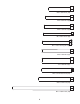
PART IDENTIFICATION CHART See the drawings below to identify small parts used in assembly. The number in parentheses below each drawing is the key number of the part, from the PART LIST near the end of this manual. Note: Some small parts may have been preattached. If a part is not in the parts bag, check to see if it has been preattached.
M10 x 63mm Bolt (105) M10 x 68mm Bolt (98) M10 x 75mm Bolt (92) M6 x 75mm Screw (96) M10 x 75mm Carriage Bolt (90) M10 x 78mm Bolt (32) 1/2" x 78mm Bolt (97) M10 x 81mm Button Bolt (104) M10 x 87mm Bolt (106) M10 x 156mm Bolt (100) 6
ASSEMBLY • Place all parts in a cleared area and remove the packing materials. Do not dispose of the packing materials until assembly is completed. Make Assembly Easier Everything in this manual is designed to ensure that the weight bench can be assembled successfully by almost anyone. By setting aside plenty of time, assembly will go smoothly. • As you assemble the weight bench, make sure all parts are oriented as shown in the drawings.
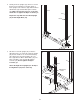
2. Identify the Rear Uprights (43), which are shorter than the Front Uprights (not shown). Attach a Rear Upright to the Left Base (40) with two M10 x 78mm Bolts (32) and two M10 Nylon Locknuts (34). Make sure that the holes are on the side shown. Do not tighten the Nylon Locknuts yet. 2 43 43 Repeat this step with the other Rear Upright (43) and the Right Base (38). Holes 34 32 38 40 3.
4. Identify the Left Safety Spotter (51), which has a round opening on the side shown. Loosen the two Adjustment Knobs (22) on the Left Safety Spotter by turning them counterclockwise. Next, pull both Adjustment Knobs at the same time and slide the Left Safety Spotter (51) onto the Left Uprights (43, 44). Then, engage the Adjustment Knobs into a set of adjustment holes in the Uprights. Do not tighten the Adjustment Knobs yet.
7. Orient the Chin-up Bar (54) as shown, and attach it to the Left Front Upright (44) and the Left Top Frame (48) with four M10 x 78mm Bolts (32), a Chrome Joint Plate (108), and four M10 Nylon Locknuts (34). Do not tighten the Nylon Locknuts yet. 7 Bend 32 32 Attach the Chin-up Bar (54) to the Right Front Upright (not shown) and the Right Top Frame (not shown) in the same way. 54 48 108 See step 4. Tighten the Adjustment Knobs (22). 44 34 8.
9. Attach the Foot Plate (67) and the Weight Carriage Base (41) to the Center Base (39) with two M10 x 81mm Button Bolts (104) and two M10 Nylon Locknuts (34). Do not tighten the Nylon Locknuts yet. 9 34 41 34 67 39 104 10. Attach the Center Top Frame (46) to the Left Top Frame (48) with two M10 x 78mm Bolts (32) and two M10 Nylon Locknuts (34). Make sure that the decal is in the indicated location. Do not tighten the Nylon Locknuts yet.
. Insert an M10 x 19mm Bolt (102) into the bracket on the Weight Carriage (62) from the side shown. 12 102 62 Slide the Weight Carriage (62) onto the Weight Carriage Upright (42) so that the weight tube is toward the Center Upright (45). Weight Tube 42 45 13. Attach the Weight Guide Top Frame (49) to the Weight Carriage Upright (42) with two M10 x 75mm Bolts (92), four M10 Washers (35), and two M10 Nylon Locknuts (34). Do not tighten the Nylon Locknuts yet.
15. Press two Plastic Butterfly Bushings (79) and two Metal Butterfly Bushings (93) into the Right Butterfly Arm (56). Wet the bottom of the Right Butterfly Arm with soapy water and slide a Butterfly Foam Pad (66) onto the Right Butterfly Arm. 15 Grease 93 79 80 97 55 79 Apply some of the included grease to a 1/2" x 78mm Bolt (97) and to the Plastic Butterfly Bushings (79). Attach the Right Butterfly Arm (56) to the Butterfly Bracket (55) with the Bolt and a 1/2" Nylon Locknut (94).
18. Route the Medium Cable (69) over a Pulley (87) and down through the Weight Guide Top Frame (49). Make sure that the Cable is routed between the Pulley and the welded rod as shown. Attach the Pulley inside the Weight Guide Top Frame with an M10 x 75mm Bolt (92), two M10 Washers (35), two 17mm Spacers (89), and an M10 Nylon Locknut (34). 18 34 35 89 87 Welded Rod 49 89 69 35 92 19. Wrap the Medium Cable (69) under a Pulley (87).
22. Identify the Butterfly Cable (31). Grease an M8 x 43mm Shoulder Bolt (107) with grease. Attach the Cable to the Left Butterfly Arm (57) with the Shoulder Bolt, an M10 Small Washer (95), and an M8 Nylon Locknut (17). 22 Grease 107 31 95 17 57 23. Wrap the Butterfly Cable (31) over a “V”-pulley (86). Attach the “V”-pulley, a Large Cable Trap (103), and two Full Pulley Guards (110) to the bracket on the Center Upright (45) with an M10 x 63mm Bolt (105) and an M10 Nylon Locknut (34).
26. Grease an M8 x 43mm Shoulder Bolt (107). Attach the Butterfly Cable (31) to the Right Butterfly Arm (56) with the Shoulder Bolt, an M10 Small Washer (95), and an M8 Nylon Locknut (17). 26 107 Grease 31 95 56 17 27. Identify the Long Cable (68). Route the eyelet end of the Cable through the Foot Plate (67) and the Center Upright (45) and under a Pulley (87).
30. Wrap the Long Cable (68) over a Pulley (87). Attach the Pulley, a Small Cable Trap (88), and two Half Pulley Guards (109) to the second set of holes from the bottom of the Pulley Plates (82) with an M10 x 48mm Bolt (33) and an M10 Nylon Locknut (34). Make sure that the Cable Trap is oriented to hold the Cable in the groove of the Pulley. 30 109 82 34 109 33 87 88 68 31.
34. Attach the Bench Frame (1) to the Bench Leg (4) with four M10 x 68mm Bolts (98), two Notched Plates (24), and four M10 Nylon Locknuts (34). Do not tighten the Nylon Locknuts yet. 34 34 1 24 4 98 24 35. Attach the Backrest Frames (6) to the Backrest Bracket (16) with four M10 x 45mm Bolts (111), four M10 Washers (35), and four M10 Nylon Locknuts (34). Make sure that the Backrest Frames are oriented with the indicated holes closer to the bottom. Do not tighten the Nylon Locknuts yet.
37. Insert the Backrest Bracket (16) into the slot in the Bench Frame (1). 37 100 Attach the Backrest Frames (6) to the Bench Frame (1) with an M10 x 156mm Bolt (100), two M10 Washers (35), and an M10 Nylon Locknut (34). Do not overtighten the Nylon Locknut; the Bracket Frames must be able to pivot easily. 35 16 6 See the inset drawing. Insert the Bench Pin (23) into the Bench Frame (1) and one of the adjustment holes in the Backrest Bracket (16). 35 1 34 See steps 32 to 35.
40. Grease an M10 x 68mm Bolt (98) with grease. Attach the Leg Lever (5) to the Bench Leg (4) with the Bolt and an M10 Nylon Locknut (34). Do not overtighten the Nylon Locknut; the Leg Lever must pivot easily. 40 4 34 5 98 41. Insert a Pad Tube (27) into the Bench Leg (4). Slide two Foam Pads (26) onto the Pad Tube. 41 Assemble the two remaining Pad Tubes (27) to the Leg Lever (5) in the same way. 27 26 4 5 27 27 26 42. Attach the Curl Pad (9) to the Curl Post (8) with two M6 x 16mm Screws (29).
ADJUSTMENT This section explains how to adjust the weight bench. See the EXERCISE GUIDELINES on page 26 for important information about how to get the most benefit from your exercise program. Also, refer to the accompanying exercise guide to see the correct form for a selection of exercises. ADJUSTING THE BACKREST To adjust the position of the Backrest (11), pull the Bench Pin (23) out of the Bench Frame (1).
ADDING WEIGHT TO THE LEG LEVER Slide the desired amount of weight onto the Weight Tube (76). To use Olympic weights, slide the Weight Adapter (18) onto the Weight Tube before adding weights. Secure the weights with the Small Weight Clip (37). 76 18 WARNING: Do not place more than 150 lbs. (68 kg) on the Weight Tube (76). 37 Weight ATTACHING ACCESSORIES Attach the Lat Bar (58) to the Medium Cable (69) with a Small Cable Clip (74).
USING THE WEIGHT RESTS AND THE SAFETY SPOTTERS 43 52 22 Before beginning an exercise, move the Weight Rests (52, 53) and the Safety Spotters (50, 51) to sets of holes in the Uprights (43, 44, and 30) that are best suited for that exercise. Do this by turning the Adjustment Knobs (22) counterclockwise until they are loose. Pull the Adjustment Knobs and slide the Weight Rests or the Safety Spotters to the desired heights.
MAINTENANCE Make sure that all parts are properly tightened each time the weight bench is used. Replace any worn parts immediately. The weight bench can be cleaned with a damp cloth and a mild, non-abrasive detergent; do not use solvents to clean the weight bench. TIGHTENING THE CABLES Woven cable, the type of cable used on the weight bench, can stretch slightly when it is first used. If there is slack in the cables before resistance is felt, the cables should be tightened.
CABLE DIAGRAM The diagram below shows the proper routing of the cables. The numbers in each drawing show the proper routing for that cable. Use the diagram to make sure that the cables and the cable traps have been assembled correctly. If the cables and cable traps are not assembled correctly, the weight bench will not function properly and damage may occur. Make sure that the cable traps do not touch or bind the cables. 4 Medium Cable (69) Length: 9 ft. 7 in. (2.
EXERCISE GUIDELINES THE FOUR BASIC TYPES OF WORKOUTS PERSONALIZING YOUR EXERCISE PROGRAM Muscle Building To increase the size and strength of your muscles, push them close to their maximum capacity. Your muscles will continually adapt and grow as you progressively increase the intensity of your exercise. You can adjust the intensity level of an individual exercise in two ways: • by changing the amount of resistance used • by changing the number of repetitions or sets performed.
The repetitions in each set should be performed smoothly and without pausing. The exertion stage of each repetition should last about half as long as the return stage. Proper breathing is important. Exhale during the exertion stage of each repetition and inhale during the return stroke. Never hold your breath. COOLING DOWN End each workout with 5 to 10 minutes of stretching. Include stretches for both your arms and legs. Move slowly as you stretch and do not bounce.
EXERCISE MONDAY Date: / EXERCISE SETS REPS WEIGHT SETS REPS / AEROBIC EXERCISE / EXERCISE FRIDAY Date: / WEIGHT / THURSDAY Date: / REPS AEROBIC EXERCISE WEDNESDAY Date: / SETS / TUESDAY Date: / WEIGHT / Make photocopies of this page for scheduling and recording your workouts.
EXERCISE MONDAY Date: / EXERCISE SETS REPS WEIGHT SETS REPS / AEROBIC EXERCISE / EXERCISE FRIDAY Date: / WEIGHT / THURSDAY Date: / REPS AEROBIC EXERCISE WEDNESDAY Date: / SETS / TUESDAY Date: / WEIGHT / Make photocopies of this page for scheduling and recording your workouts.
PART LIST—Model No. WEBE3777.0 Key No. Qty. 1 2 3 4 5 6 7 8 9 10 11 12 13 14 15 16 17 18 19 20 21 22 23 24 25 26 27 28 29 30 31 32 33 34 35 36 37 38 39 40 41 42 43 44 45 46 47 48 49 50 1 1 1 1 1 2 1 1 1 1 1 4 2 6 2 1 3 1 1 4 1 6 1 2 2 6 3 6 6 1 1 36 5 74 26 17 1 1 1 1 1 1 2 1 1 1 1 1 1 1 Description Key No. Qty.
Key No. Qty. 101 102 103 104 105 106 107 108 109 110 111 1 1 2 2 2 1 2 2 10 4 4 Description Key No. Qty. Butterfly Backrest M10 x 19mm Bolt Large Cable Trap M10 x 81mm Button Bolt M10 x 63mm Bolt M10 x 87mm Bolt M8 x 43mm Shoulder Bolt Chrome Joint Plate Half Pulley Guard Full Pulley Guard M10 x 45mm Bolt * * * * * * * * * * – – – – – – – – – – Description User’s Manual Exercise Chart Hex Key Grease Packet 7' Barbell 2.5-lb. Weight 5-lb. Weight 10-lb. Weight 25-lb. Weight 45-lb.
EXPLODED DRAWING A—Model No. WEBE3777.
EXPLODED DRAWING B—Model No. WEBE3777.
EXPLODED DRAWING C—Model No. WEBE3777.
EXPLODED DRAWING D—Model No. WEBE3777.
ORDERING REPLACEMENT PARTS To order replacement parts, please see the front cover of this manual. To help us assist you, be prepared to provide the following information when contacting us: • the model number and serial number of the product (see the front cover of the manual) • the name of the product (see the front cover of this manual) • the key number and description of the part(s) (see the PART LIST and the EXPLODED DRAWING near the end of this manual) LIMITED WARRANTY ICON Health & Fitness, Inc.