Model No. WEBE37330 Serial No. Write the serial number in the space above for future reference. USER’S MANUAL Serial Number Decal (Under Seat) QUESTIONS? As a manufacturer, we are committed to providing complete customer satisfaction. If you have questions, or if there are missing or damaged parts, we will guarantee complete satisfaction through direct assistance from our factory. TO AVOID DELAYS, PLEASE CALL DIRECT TO OUR TOLLFREE CUSTOMER HOT LINE.
TABLE OF CONTENTS WARNING DECAL PLACEMENT . . . . . . . . . . . . . . . . . . . . . . . . . . . . . . . . . . . . . . . . . . . . . . . . . . . . . . . . . . 3 IMPORTANT PRECAUTIONS . . . . . . . . . . . . . . . . . . . . . . . . . . . . . . . . . . . . . . . . . . . . . . . . . . . . . . . . . . . . . 4 BEFORE YOU BEGIN . . . . . . . . . . . . . . . . . . . . . . . . . . . . . . . . . . . . . . . . . . . . . . . . . . . . . . . . . . . . . . . . . . . 5 ASSEMBLY . . . . . . . . . . . . . . . . . . . . . .
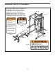
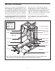
WARNING DECAL PLACEMENT The decals shown here have been placed on the weight bench. If a decal is missing or illegible, please call our Customer Service Department toll-free at 1-800-999-3756, Monday through Friday, 6 a.m. until 6 p.m. Mountain Time, to order a free replacement decal. Apply the decal in the location shown. Decal 2 Decal 2 ! WARNING • Misuse of this product may result in serious injury. Keep hands and fingers clear of this area.
IMPORTANT PRECAUTIONS WARNING: To reduce the risk of serious injury, read the following important precautions before using the weight bench. 1. Read all instructions in this manual before using the weight bench. Use the weight bench only as described in this manual. 10. Always set both weight rests and both safety spotters at the same height. 11. The weight bench is designed to support a maximum user weight of 300 pounds and a maximum total weight of 610 pounds.
BEFORE YOU BEGIN Thank you for selecting the versatile WEIDER® CLUB C670 weight bench. The weight bench offers a selection of weight stations designed to develop every major muscle group of the body. Whether your goal is to tone your body, build dramatic muscle size and strength, or improve your cardiovascular system, the weight bench will help you to achieve the specific results you want. Department toll-free at 1-800-999-3756, Monday through Friday, 6 a.m. until 6 p.m. Mountain Time (excluding holidays).
ASSEMBLY • As you assemble the weight bench, make sure all parts are oriented as shown in the drawings. Make Things Easier for Yourself Everything in this manual is designed to ensure that the weight bench can be assembled successfully by anyone. However, it is important to realize that the versatile weight bench has many parts and that the assembly process will take time. Most people find that by setting aside plenty of time, assembly will go smoothly.
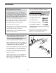
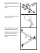
2. Attach a Small Base Cap (20) to the Bench Base (3) with two M4 x 16mm Screws (36). Attach the other Small Base Cap in the same manner. 2 14 Press the 51mm x 76mm Inner Cap (14) into the indicated end of the Bench Leg (4). 4 34 Attach the Bench Leg (4) to the Bench Base (3) with four M10 x 71mm Bolts (31), two Bench Base Joint Plates (25), and four M10 Nylon Locknuts (34). Do not tighten the Locknuts yet. 20 25 31 25 3 31 20 36 3.
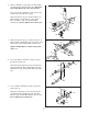
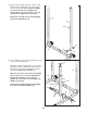
6. Pull out the Small Adjustment Knob (23) that is nearer the Stabilizer (2). Insert the Backrest Bracket (16) between the tubes on the Bench Frame (1) and engage the Small Adjustment Knob into one of the holes in the Bracket. 6 34 99 35 23 6 23 Pull out the Small Adjustment Knob (23) by the Seat Bracket Sleeve (93). Insert the Seat Bracket (17) into the Seat Bracket Sleeve and engage the Small Adjustment Knob into one of the holes in the Bracket.
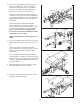
10. Press two 25mm Square Inner Caps (28) into a Pad Tube (27). Slide the Pad Tube into a hole in the Leg Lever (5). Slide two Foam Pads (26) onto the Pad Tube. 10 5 27 Assemble the other Pad Tube (27) in the same manner. 26 28 27 26 28 11. Press a 45mm Square Inner Cap (12) into the bottom of the Curl Post (8). 11 9 Attach the Curl Pad (9) to the Curl Post (8) with two M6 x 16mm Screws (29). 8 29 12 12. Attach a Large Base Cap (70) to the Left Base (40) with two M4 x 16mm Screws (36).
13. Attach a Rear Upright (43) to the Left Base (40) with two M10 x 78mm Bolts (32) and two M10 Nylon Locknuts (34). Note: The Rear Uprights are shorter than the Front Uprights (not shown). Make sure the holes are on the side shown. Do not tighten the Locknuts yet. 13 Repeat this step with the other Rear Upright (43) and the Right Base (38). 43 43 Holes 34 32 38 40 14. Press a 60mm Square Inner Cap (64) into the top of the Left Front Upright (44).
15. Loosen the two Adjustment Knobs (22) on the Left Safety Spotter (51) by turning them counterclockwise. Pull both Knobs out at the same time and slide the Left Safety Spotter (51) onto the Left Uprights (43, 44) and engage and tighten the Adjustment Knobs (22) into a set of holes in the Uprights. 15 51 22 Repeat this step with the Right Safety Spotter (50) and Right Uprights (not shown). 22 43 50 16. Loosen the Adjustment Knob (22) on the Right Weight Rest (52) by turning it counterclockwise.
18. Attach the Chin-up Bar (54), with the bends going up, to the Left Front Upright (44) and the Left Top Frame (48) with four M10 x 78mm Bolts (32), a Rack Joint Plate (85), and four M10 Nylon Locknuts (34). Do not tighten the Locknuts yet. 18 Bend Attach the Chin-up Bar (54) to the Right Front Upright (not shown) and the Right Top Frame (not shown) in the same manner. 32 32 54 48 85 44 34 19.
20. Press a 60mm Square Inner Cap (64) into the Weight Guide Base (41). 20 64 34 Attach the Foot Plate (67) and the Weight Guide Base (41) to the Center Base (39) with two M10 x 81mm Button Bolts (104) and two M10 Nylon Locknuts (34). Do not tighten the Locknuts yet. 41 34 67 39 104 21. Attach the Center Top Frame (46) to the Left Top Frame (48) with two M10 x 78mm Bolts (32) and two M10 Nylon Locknuts (34). Make sure the decal is in the indicated location. Do not tighten the Locknuts yet.
23. Press two 48mm Weight Carriage Caps (63) into the Weight Carriage (62). 23 102 63 62 Insert an M10 x 19mm Bolt (102) into the bracket on the Weight Carriage (62) from the side shown. Slide the Weight Carriage (62) onto the Weight Guide Upright (42) so that the weight tube is toward the Center Upright (45). Weight Tube 63 42 45 24. Press two 60mm Square Inner Caps (64) into the Weight Guide Top Frame (49).
26. Press a 50mm Square Inner Cap (13) and a 25mm Square Inner Cap (28) into the Right Butterfly Arm (56). Wet the bottom of the Butterfly Arm with soapy water and slide a Butterfly Foam Pad (66) onto the Arm. 26 80 Lubricate 79 Lubricate a 1/2” x 78mm Bolt (97) and the Butterfly Bushings (79) with grease. Attach the Right Butterfly Arm (56) to the Butterfly Bracket (55) with the Bolt and a 1/2” Nylon Locknut (94). Cover the Bolt and Locknut with two Butterfly Caps (80).
29. Locate the Medium Cable (69). Route the Cable up through the Weight Guide Top Frame (49) and over a Pulley (87). Attach the Pulley inside the Top Frame with an M10 x 75mm Bolt (92), two M10 Washers (35), two 17mm Spacers (89), and an M10 Nylon Locknut (34). 29 49 87 34 35 89 35 89 92 69 30. Route the Medium Cable (69) over a Pulley (87) and down through the Weight Guide Top Frame (49).
34. Locate the Butterfly Cable (109). Attach the Cable to the Left Butterfly Arm (57) with an M8 x 43mm Shoulder Bolt (107), an M10 Small Washer (95), and an M8 Nylon Locknut (108). 34 107 109 95 108 57 35. Wrap the Butterfly Cable (109) over a “V”-pulley (86). Attach the “V”-pulley and a Large Cable Trap (111) to the bracket on the Center Upright (45) with an M10 x 60mm Bolt (105) and an M10 Nylon Locknut (34). Make sure the Cable Trap is oriented to hold the Cable in the groove of the Pulley.
39. Locate the Long Cable (68). Route the eyelet end of the Cable through the Foot Plate (67) and the Center Upright (45), and under a Pulley (87). 39 45 87 Attach the Pulley (87) inside the Center Upright (45) with an M10 x 75mm Bolt (92), two M10 Washers (35), two 17mm Spacers (89), and an M10 Nylon Locknut (34). Note: The Foot Plate (67) is shown pulled away from the Center Upright for clarity. 34 35 89 89 68 67 40. Wrap the Long Cable (68) over a Pulley (87).
ADJUSTMENTS This section explains how to adjust the weight bench. See the EXERCISE GUIDELINES on page 24 for important information about how to get the most benefit from your exercise program. Also, refer to the accompanying exercise guide to see the correct form for each exercise. Make sure all parts are properly tightened each time the weight bench is used. Replace any worn parts immediately. The weight bench can be cleaned with a damp cloth and a mild, non-abrasive detergent. Do not use solvents.
ADDING WEIGHT TO THE LEG LEVER 5 To add weight (not included) to the Leg Lever (5), slide the desired amount of weight onto the weight tube. Weight Tube WARNING: Do not place more than 150 pounds on the Leg Lever (5). Weight ADDING WEIGHT TO THE WEIGHT CARRIAGE To add weight (not included) to the Weight Carriage (62), slide the desired amount of weight onto the weight tube. Secure the weight with a Weight Clip (71). 62 Weight WARNING: Do not place more than 150 pounds on the Weight Carriage (62).
ATTACHING THE DIP ARM To attach the Dip Arm (60), first move a Safety Spotter (50 or 51) to the highest position possible (see USING THE WEIGHT RESTS AND SAFETY SPOTTERS below). Attach the Dip Arm to the outside of the Safety Spotter with two M10 x 97mm Carriage Bolts (101) and two M10 Nylon Locknuts (34). Make sure the warning decal is in the indicated location. 101 101 Decal 60 WARNING: Always set 75 pounds on the Weight Carriage (not shown) before using the Dip Arm (60).
MOVING THE BENCH To move the weight bench, lift the Bench Leg (4) so that the bench pivots onto the Wheels (21). Roll the bench to the desired location and set the Bench Leg down. 21 4 TIGHTENING THE CABLES Woven cable, the type of cable used on the weight rack, can stretch slightly after it is first used. If there is slack in the cables, tighten them by removing the M10 x 45mm Bolt (33) and the M10 Nylon Locknut (34) attaching the lower Pulley (87) and Cable Trap (88) to the two Pulley Plates (82).
CABLE DIAGRAMS The cable diagrams below show the proper routing of the Long Cable (68), the Medium Cable (69), and the Butterfly Cable (109). Use the diagram to make sure that the cables and the cable traps have been assembled correctly. If the cables have not been correctly routed, the weight rack will not function properly and damage may occur. The numbers show the correct route for each cable. Make sure that the cable traps do not touch or bind the cables.
EXERCISE GUIDELINES THE FOUR BASIC TYPES OF WORKOUTS PERSONALIZING YOUR EXERCISE PROGRAM Muscle Building To increase the size and strength of your muscles, push them close to their maximum capacity. Your muscles will continually adapt and grow as you progressively increase the intensity of your exercise. You can adjust the intensity level of an individual exercise in two ways: • by changing the amount of resistance used • by changing the number of repetitions or sets performed.
Rest for a short period of time after each set. The ideal resting periods are: • Rest for three minutes after each set for a muscle building workout. • Rest for one minute after each set for a toning workout. • Rest for 30 seconds after each set for a weight loss workout. Plan to spend the first couple of weeks familiarizing yourself with the equipment and learning the proper form for each exercise. slowly as you stretch and do not bounce.
EXERCISE MONDAY WEIGHT SETS REPS WEIGHT SETS REPS WEIGHT SETS REPS Date: / / AEROBIC EXERCISE TUESDAY Date: / / WEDNESDAY EXERCISE Date: / / THURSDAY AEROBIC EXERCISE Date: / / EXERCISE FRIDAY Date: / / Make photocopies of this page for scheduling and recording your workouts.
EXERCISE MONDAY WEIGHT SETS REPS WEIGHT SETS REPS WEIGHT SETS REPS Date: / / AEROBIC EXERCISE TUESDAY Date: / / WEDNESDAY EXERCISE Date: / / THURSDAY AEROBIC EXERCISE Date: / / EXERCISE FRIDAY Date: / / Make photocopies of this page for scheduling and recording your workouts.
PART IDENTIFICATION CHART—Model No.
M6 x 75mm Screw (96) M10 x 75mm Carriage Bolt (90) M10 x 78mm Bolt (32) 1/2" x 78mm Bolt (97) M10 x 81mm Button Bolt (104) M10 x 85mm Bolt (103) M10 x 87mm Bolt (106) M10 x 94mm Bolt (98) M10 x 102mm Bolt (99) M10 x 97mm Carraige Bolt (101)
25mm Square Inner Cap (28) 51mm x 76mm Inner Cap (14) 45mm Square Inner Cap (12) 38mm x 50mm Inner Cap (15 ) 50mm Square Inner Cap (13) 48mm Round Inner Cap (19) 60mm Square Inner Cap (64) 48mm Weight Carriage Cap (63)
PART LIST—Model No. WEBE37330 Key No. Qty.
EXPLODED DRAWING—Model No.
34 34 34 64 85 85 52 84 110 84 32 85 32 22 32 32 85 84 53 85 84 54 36 44 64 70 77 34 36 84 36 84 34 85 76 22 34 75 50 36 32 76 32 38 22 77 22 32 75 32 84 36 43 84 84 84 34 22 51 70 67 66 80 84 34 112 22 28 80 95 107 108 79 79 36 32 47 13 56 104 32 34 32 34 84 34 90 80 94 97 80 34 101 32 70 101 79 39 108 79 28 32 55 109 64 68 34 35 61 60 34 34 66 59 87 89 45 111 34 13 32 57 36 95 107 59
ORDERING REPLACEMENT PARTS To order replacement parts, simply call our Customer Service Department toll-free at 1-800-999-3756, Monday through Friday, 6 a.m. until 6 p.m. Mountain Time (excluding holidays). To help us assist you, please be prepared to give the following information: 1. The MODEL NUMBER of the product (WEBE37330) 2. The NAME of the product (WEIDER® CLUB C670 weight bench) 3. The SERIAL NUMBER of the product (see the front cover of this manual) 4.