Model No. WESY59421 Serial No. Write the serial number in the space above for future reference. CR SS Serial Number Decal (under seat) QUESTIONS? USER'S MANUAL As a manufacturer, we are commitred to providing complete customer satisfaction. If you have questions, or if there are missing or damaged parts, we will guarantee complete satisfaction through direct assistance from our factory. TO AVOID DELAYS, PLEASE CALL DIRECT TO OUR TOLLFREE CUSTOMER HOT LINE.
TABLE OF CONTENTS WARNING DECAL PLACEMENT .......................................................... IMPORTANT PRECAUTIONS ............................................................. BEFORE YOU BEGIN ................................................................... ASSEMBLY ........................................................................... ADJUSTMENTS ...................................................................... CABLE DIAGRAM ............................................................
IMPORTANT _WARN PRECAUTIONS ING: To .du. _. before using the resiStance system. risk of asdous injury, Bad the following Important precautions 1. Read ell inatructions In this manuel before using the resistance system. Uas the resistance system only as described In this manuaL 2. It is the responsibility of the owner to ensure that all users of the resistance system are adequately Informed of ell precoutinno. 3. The resistam:e system is Intandad for home use only.
BEFORE YOU BEGIN Thank you for selectingthe innovativeCrossBow by WELDER resistancesystem. The resistance system offers a selectionof stationsdesignedto develop every major muscle groupof the body. Whether your goal is to tone your body, builddramaticmuscle size and strength,or improveyour cardiovascularsystem, the resistancesystem will help you to achieve the specific resultsyou want.
ASSEMBLY • Tighten all parts as you assemble them. unless instructedto do otherwise. Make Thk'tg= F.al_r for Youmeif TNsm_ual _s€_ned.to_ thatmerestante_ canhe'assembled s_ by • As you assemble the resistance system, make sure all parts are odented as shown in the drawings most people, However, it I_,i_= ntt0 reallz8 that the versatile re,stance system has r_ny partsandtt_t'theas_ pro=='_ll take Ume.M_t _op_ _ _at W s6_ngask_pk_ty of_. assemUy _ g0_=_t_y. The included IAIlen wrenche.e.e.e.e.e.e.e.
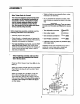
2. Attach a Wheel (31) to the outside of the Base (1) with an M10 x 108mm Bolt (81), three M10 Washers (75), and an M1O Nylon Locknut(76). Do not overtighten the Nylon Locknut; the Wheel must be able to turn easily. Attach the other Wheel (not shown) in the same manner. -TZ.'-] 3. Press a 38mm x 64mm inner Cap (41) into each end of the Cross Tube (11). 75 Orient the Cross Tube (11) as shown, with the welded tubes at the bottom.
6. Attach the Lat Tower (4) to the Upright (3) with four M10 x 25mm Button Head Bolts (87), and four M19 Lock Washers (103). Attach the Name Plate (89) to the Lat Tower (4) with t_o M4 x 16mm Screws (62). 62 _. °° : 103 -3 7. Press a 38mm Round Inner Cap (38) into each end of the Lat Tower Crossbar (10). 70 65 Attach two Eyebolts (34) to the Lat Tower Crossbar (10) with two M8 Washers (59) and two M8 Nylon Locknuts (65). Do not overtighten the Loeknuts; the Eyebolts must be able to rotate freely.
g. Attach two 8mm Metal Spacers (97), a 60mm Metal Spacer (39), and two Bearing Wheels (46) to one end of the Seat Carriage (12) with an M8 x 104mm Bolt (60) and an M8 Nylon Locknut (65) as shown. Be sure the parts are oriented as shown in the inset drawing; the Seat Knob (not shown) will not engage the Bench Rail (not shown) if they are incorrectly oriented. Do not overtighten the Locknut; the Bearing Wheels must be able to roll easily. 9 12 6L _Attach _-._ • 97 -"_€'_ second ./_.
i2. Press two 25mm Square Inner Caps (54) into the indicated end of the Backrest Frame (15). 12 Attach a Plastic Foot (53) to the Backrest Frame (15) with an M4 x 16ram Screw (62). SS Attach the two Guard Plates (17) to the inside of the Backrest Frame (15) with four M4 x 16mm Screws (62). . 53 L=-li :joo 17_/_ L' 62 L" 17 13. Odent the Backrest (14) and the Backrest Backing (8) as shown. Attach the Backrest and the Backrest Backing to the Backrest Frame (15) with four M6 x 45mm Bolts (58).
16. Locate the Crossbow Fulcrum (18) on the Lat Tower (4) (see the inset drawing). Slide the Crossbow Spacer (35) onto the rods on the Crossbow Fulcrum. Make sure the Spacer is oriented as shown in the drawing. 16 86 up Set the Crossbows intothe CrossbowSpacer (35) in the followingorder: the 1O-PoundRemovable Crossbow(67), the 20-Pound Removable Crossbow(36), an 80-Pound Crossbow(95), the 10-Pound Center Crossbow(44), an 8O-Pound Crossbow(95), and the 40-Pound Crossbow(96).
20. Wrap the Long Cable (80) under a 90mm Pulley (28) as shown. Attach the Pulley and a Pulley Guard (29) to the Upright (3) with an M10 x 113mm Button Head Bolt (40) and an M10 Nylon Locknut (76). Be sure the fiat edge of the Pulley Guard is on the bottom. 2O 80 Flat Edge 21. Attach a Pulley Housing (94) to the indicated "U'channel on the lO-Pound Center Crossbow (44) with an M10 x 102mm Button Head Bolt (24), two Pivot Bushings(74), and an M10 Nylon Locknut (76).
24.Locatethe LegLeverCable(32),whichhastwo endsthatarethesamelengthanda thirdend thatislonger. 24 RoutethelongestendoftheLegLeverCable (32)throughtheholeintheFrontLeg(6),and attachit insideoftheholeintheLegLever(7) withanM10x 6Omm Bolt(63)and an M10 Nylon Locknut (76). 25. Attach a 90mm Pulley (28) inside of the hole in the Front Leg (6) with an M10 x 91ram Bolt (90), two 26mm Spacers (52), two M10 Washers (75), end an MI0 Nylon Locknut (76). Be sure the Pulley is above the Leg Lever Cable (32).
ADJUSTMENTS This section explains how to adjust the resistance system. See the EXERCISE GUIDELINES on page 17 for importantinformationabout how to get the most benefit from your exercise program. Also, refer to the accompanying exercise guide to see the correct form for each exercise. Make sure all parts are propedy tightened each time you use the resistancesystem. Replace worn parts immediately. The resistancesystem can be cleaned with a damp clothand a mild, non-abrasive detergent. Do not use solvents.
A'I-fACHING THE ACCESSORIES 33 \ To attach a Short Handle (49) to a high pulley,flint attach the htgh pulley to the resistancesystem (see ATTACHING THE HIGH PULLEYS AND LEG LEVER on page 13). Then, attach the Short Handle to the Short Cable (33) with a Cable Clip (51). 4c The Long Handles (not shown) and the Ankle Strap (not shown) can be attached to the Long Cable (80) wtthCable Clips (51).
ADJUSTING THE BACKREST The Backrest (14) can be used in a level positionor one of three inclined positions. To use the Backrest in a level position,secure the Seat Frame (12) to the adjustment hole in the Bench Rail (5) next to the Front Leg (6) (see ADJUSTING THE SEAT on page 13). To use the Backrest (14) in an inclined position, secure the Seat Frame (12) to one of the other three adjustment holes in the Bench Rail (5). Rest the Backrest against the Upright (3).
USING THE REMOVABLE CROSSBOWS The Removable Crossbows (36, 67) can be used to exercise apart from the resistancesystem, as shown in the video or on the exemise guide. To remove a Crossbow,pull it out of the CrossbowSpacer (35). 67 36 To replace the Removable Crossbows (36, 67), slide them into the Crossbow Spacer (35) from the side shown, so that the arrows on the rings point toward the Crossbow Spacer. Make sure the rings are pushed against the Crossbow Spacer.
EXERCISE GUIDELINES THE FOUR BASIC TYPES OF WORKOUTS PERSONALIZING YOUR EXERCISE PROGRAM Muscle Building To increase the size and strength of your muscles, push them close to their maximum capacity.Your muscles will continuallyadapt and grow as you progressively increase the intensityof your exercise. You can adjust the intensity level of an individualexercise in two ways: • by changing the amount of resistance used • by changing the number of repetitions or sets performed.
Rest for a short period of time after each set. The ideal resting periods are: • Rest for three minutes after each set for a muscle building workout. • Rest for one minute after each set for a toning workout. • Rest for 30 seconds after each set for a weight less workout. Plan to spend the first couple of weeks familiarizing yourself with the equipment and learning the proper form for each exercise. slowly as you stretch and do not bounce.
MONDAY EXERCISE RESISTANCE SETS REPS RESISTANCE SETS REPS RESISTANCE SETS REPS Date: / / AEROBIC EXERCISE TUESDAY Date: I / WEDNESDAY EXERCISE Da_: / / THURSDAY AEROBIC EXERCISE Date: I I FRIDAY EXERCISE Date: / / Make photocopiesof this page for schedulingand recordingyour workouts.
ORDERING REPLACEMENT PARTS To order replacement pads, simply cell our Customer Service Department toll-free at 1-800-999-3756, Monday through Fdday, 6 a.m. until 6 p.m. Mountain Time (excluding holidays).
PART IDENTIFICATION CHART Refer to the drawings below to identify small parts used in assembly.The number in parentheses below each drawing is the key number of the part, from the PART LIST on the reverse side of this page. Note: Some small parts may have been pre-attached. If a part is not in the parts bag, check to see if it has been pre-attached.
_\\\\\\\1 -_ M10 x 65mm Button Head Bolt (70) M10 x 53ram Carraige Bolt (61) _\\\\\\\1 M10 x 68ram Bolt (56) M10 x 6Omm Bolt (63) _\\\\\\\1 _\\\\\\ M10 X 66mm Carriage Bolt (83) M8 x 45ram Bolt (58) _\\\\\\\l M10 x 72ram Bolt (64) M10 x 42ram Button Head Bolt (71) _\\\\\\\1 M10 x 91mm Bolt (90) M10 x 25ram Button Head Bolt (87) _\\\\\\\\\\\\\\\\\\\ ,_ M10 x 103ram Bolt (66) M4 x 19mm Screw (77) &\\\\\\\\\\\\\\\\ I M8 x 104mm Bolt (60) M8 x 19ram Button Head Screw (86) M10 x 102mm Button Hea
PART LISTmModel Key No. Qty. 1 2 3 4 5 6 7 8 9 10 11 12 13 14 15 16 17 18 19 20 21 22 23 24 25 26 27 28 29 30 31 32 33 34 35 36 37 38 39 40 41 42 43 44 45 46 47 48 49 50 51 52 53 54 55 1 1 1 1 1 1 1 1 1 1 1 1 1 1 1 1 2 1 2 2 2 2 2 2 4 4 1 10 3 1 2 1 2 2 1 1 2 2 3 1 2 2 1 1 1 6 2 1 2 1 4 2 3 2 1 No.
EXPLODED DRAWINGmModel No. WESY59421 R1202B 86 96 79 44 36 21 101 8 67 62 15 ,, 62 _.-_8 .-" 87 .