Model No. WECCBE1137.0 Serial No. Write the serial number in the space above for future reference. USER'S MANUAL Serial Number Decal QUESTIONS? As a manufacturer, we are committed to providing complete customer satisfaction. If you have questions, or if parts are damaged or missing, PLEASE CONTACT OUR CUSTOMER SERVICE DEPARTMENT DIRECTLY. 1-888-936-4266 CALL TOLL-FREE: Mon.–Fri., 8:00 until 17:00 EST (excluding holidays) OR E-MAIL US: customerservice@iconcanada.
TABLE OF CONTENTS WARNING DECAL PLACEMENT . . . . . . . . . . . . . . . . . . . . . . . . . . . . . . . . . . . . . . . . . . . . . . . . . . . . . . . . . . . . . .2 IMPORTANT PRECAUTIONS . . . . . . . . . . . . . . . . . . . . . . . . . . . . . . . . . . . . . . . . . . . . . . . . . . . . . . . . . . . . . . . .3 BEFORE YOU BEGIN . . . . . . . . . . . . . . . . . . . . . . . . . . . . . . . . . . . . . . . . . . . . . . . . . . . . . . . . . . . . . . . . . . . . . .4 PART IDENTIFICATION CHART . . . . .
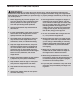
IMPORTANT PRECAUTIONS WARNING: To reduce the risk of serious injury, read all important precautions and instructions in this manual and all warnings on your weight bench before using your weight bench. ICON assumes no responsibility for personal injury or property damage sustained by or through the use of this product. 10. The weight bench is designed to support a maximum user weight of 300 lbs. (136 kg), and a maximum total weight of 410 lbs. (186 kg). Do not place more than 110 lbs.
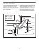
BEFORE YOU BEGIN reading this manual, please see the front cover of this manual. To help us assist you, note the product model number and serial number before contacting us. The model number and the location of the serial number decal are shown on the front cover of this manual. Thank you for selecting the WEIDER® PRO 256 weight bench. The versatile weight bench is designed to develop every major muscle group of the body.
PART IDENTIFICATION CHART This chart is provided to help you identify the small parts used in assembly. The number in parenthesis below each part refers to the key number of the part from the PART LIST near the end of this manual. Important: Note: Some small parts may have been preattached. If a part is not in the parts bag, check to see if it has been preattached.
ASSEMBLY • For help identifying small parts, use the PART IDENTIFICATION CHART on page 5. Make Things Easier for Yourself Everything in this manual is designed to ensure that the weight bench can be assembled successfully by almost anyone. By setting aside plenty of time, assembly will go smoothly. • As you assemble the weight bench, make sure all parts are oriented as shown in the drawings. • Tighten all parts as you assemble them, unless instructed to do otherwise.
3. Attach the Front Leg (8) to the Frame (2) with two M8 x 43mm Bolts (39), four M8 Washers (16), and two M8 Nylon Locknuts (17); do not tighten the Nylon Locknuts yet. 3 16 39 16 8 4. Attach the Frame (2) to the Crossbar (3) with three M8 x 55mm Bolts (18), two M8 Washers (16), and three M8 Nylon Locknuts (17); do not tighten the Nylon Locknuts yet. 2 16 17 4 18 16 2 5. Apply some of the included grease to an M10 x 63mm Bolt (32).
7. Attach the Backrest Tubes (5) to the Backrest (6) with four M6 x 38mm Screws (30) and four M6 Washers (26); do not tighten the Screws yet. 7 6 26 5 26 30 30 8. Insert the Support Rod (7) into a set of holes in the Uprights (1). Rotate the Support Rod to the locked position, with the locking pin wrapped around the left Upright. 8 Grease 1 1 34 Grease an M10 x 137mm Bolt (36).
11. Attach a Fly Arm (25) to an Upright (1) with an M10 x 120mm Bolt (19) and an M10 Nylon Locknut (33). Make sure that the Fly Arm is on the outside of the Fly Arm Stop (15). Do not overtighten the Nylon Locknut; the Fly Arm must pivot easily. 11 25 1 Attach the other Fly Arm (25) in the same way. 25 19 12. Insert an Arm Pad Tube (12) into the indicated hole in a Fly Arm (25) from the side shown. Next, slide a Foam Pad (23) onto the Arm Pad Tube; the Foam Pad will hold the Arm Pad Tube in place.
ADJUSTMENT The steps below explain how the weight bench can be adjusted. See the accompanying exercise guide to see the correct form for several exercises. Make sure all parts are properly tightened each time the weight bench is used. Replace any worn parts immediately. The weight bench can be cleaned with a damp cloth and a mild, non-abrasive detergent; do not use solvents.
ATTACHING WEIGHTS TO THE BARBELL Slide an equal amount of Weight (38, 44) onto each end of the barbell. Slide the two Lock Collars (42) against the Weights, and tighten them fully. 38 WARNING: Always secure the Weights (38, 44) on the barbell with the Lock Collars (42). Never use the barbell with more than 100 lbs. (45 kg). 42 ATTACHING THE CURL PAD 44 38 44 Barbell 45 For some exercises, the Curl Pad (45) must be attached to the weight bench.
EXERCISE GUIDELINES THE FOUR BASIC TYPES OF WORKOUTS PERSONALIZING YOUR EXERCISE PROGRAM Muscle Building To increase the size and strength of your muscles, push them close to their maximum capacity. Your muscles will continually adapt and grow as you progressively increase the intensity of your exercise. You can adjust the intensity level of an individual exercise in two ways: • by changing the amount of resistance used • by changing the number of repetitions or sets performed.
Rest for a short period of time after each set. The ideal resting periods follow: • Rest for three minutes after each set for a muscle building workout. • Rest for one minute after each set for a toning workout. • Rest for 30 seconds after each set for a weight loss workout. Plan to spend the first couple of weeks familiarizing yourself with the equipment and learning the proper form for each exercise. slowly as you stretch and do not bounce.
PART LIST—Model No. WECCBE1137.0 Key No. 1 2 3 4 5 6 7 8 9 10 11 12 13 14 15 16 17 18 19 20 21 22 23 24 Qty. 2 1 1 1 2 1 1 1 8 2 1 2 1 4 2 10 11 7 2 1 4 9 6 5 Description Upright Frame Crossbar Leg Lever Backrest Tube Backrest Support Rod Front Leg 19mm Round Inner Cap Long Pad Tube Seat Arm Pad Tube Stabilizer Plastic Bushing Fly Arm Stop M8 Washer M8 Nylon Locknut M8 x 55mm Bolt M10 x 120mm Bolt 25mm Round Angled Cap 38mm Square Inner Cap 30mm Square Inner Cap Foam Pad 25mm Round Inner Cap Key No.
EXPLODED DRAWING—Model No. WECCBE1137.
ORDERING REPLACEMENT PARTS To order replacement parts, please see the front cover of this manual.