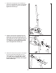
Model No. WESY3964.1 Serial No. Write the serial number in the space above for reference. USER’S MANUAL Serial Number Decal (under seat) QUESTIONS? As a manufacturer, we are committed to providing complete customer satisfaction. If you have questions, or if a part is damaged or missing, PLEASE CONTACT OUR CUSTOMER SERVICE DEPARTMENT DIRECTLY. CALL TOLL-FREE: 1-877-992-5999 Mon.–Fri., 6 a.m.–6 p.m. MST ON THE WEB: www.weiderservice.
TABLE OF CONTENTS WARNING DECAL PLACEMENT . . . . . . . . . . . . . . . . . . . . . . . . . . . . . . . . . . . . . . . . . . . . . . . . . . . . . . . . . . . . . 2 IMPORTANT PRECAUTIONS . . . . . . . . . . . . . . . . . . . . . . . . . . . . . . . . . . . . . . . . . . . . . . . . . . . . . . . . . . . . . . . . 3 BEFORE YOU BEGIN . . . . . . . . . . . . . . . . . . . . . . . . . . . . . . . . . . . . . . . . . . . . . . . . . . . . . . . . . . . . . . . . . . . . . . 4 ASSEMBLY . . . . . . . . . . . . .
IMPORTANT PRECAUTIONS WARNING: To reduce the risk of serious injury, read the following important precautions before using the weight system. 1. Read all instructions in this manual and all warnings on the weight system before using the weight system. Use the weight system only as described in this manual. 9. Always wear athletic shoes for foot protection while exercising. 10. Make sure that the cables remain on the pulleys at all times.
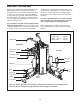
BEFORE YOU BEGIN Thank you for selecting the versatile WEIDER® PRO 4850 weight system. The weight system offers an impressive array of weight stations designed to develop every major muscle group of the body. Whether your goal is to tone your body, build dramatic muscle size and strength, or improve your cardiovascular system, the weight system will help you to achieve the specific results you want. model number and serial number before calling. The model number is WESY3964.1.
ASSEMBLY remove the packing materials. Do not dispose of the packing materials until assembly is completed. Make Assembly Easier for Yourself Everything in this manual is designed to ensure that the weight system can be assembled successfully by almost anyone. Before beginning assembly, make sure to read the information on this page. This brief introduction will save you much more time than it takes to read it.
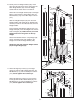
1 Frame Assembly 1. Before beginning assembly, make sure you understand the information in the box on page 5. Refer to the PART IDENTIFICATION CHART in the center of this manual for help identifying small parts. 1 Insert four M8 x 75mm Carriage Bolts (84) up through the Right Base (1). Note: It may be helpful to place a piece of tape over the bolt heads to hold them in place. 84 84 2. Insert four M8 x 75mm Carriage Bolts (84) up through the Left Base (2).
5. Attach the Rear Upright (6) to the Rear Base (3) with the two indicated M8 x 75mm Carriage Bolts (84) and two M8 Nylon Locknuts (115). Do not tighten the Locknuts yet. 5 6 3 115 115 84 6. Attach the Right Upright (4) to the Right Base (1) with the two indicated M8 x 75mm Carriage Bolts (84) and two M8 Nylon Locknuts (115). Do not tighten the Locknuts yet.
7. Attach the Left Upright (5) to the Left Base (2) with the two indicated M8 x 75mm Carriage Bolts (84) and two M8 Nylon Locknuts (115). Do not tighten the Locknuts yet. 7 5 115 115 84 8. Hold the Left Top Frame (8) between the Left Upright (5) and the Rear Upright (6). Attach the Pull-up Arm (19) and the Left Top Frame to the Rear Upright with two M8 x 83mm Bolts (89), two M8 Washers (117), and two M8 Nylon Locknuts (115). Make sure the indicated handles point up. Do not tighten the Locknuts yet.
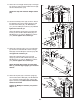
10. Identify the Front Weight Guides (136), which have the lock holes closer to the center than the Rear Weight Guides (24). Orient the Weight Guides with the holes closer to the bottom. 10 136 24 Attach the Front Weight Guides (136) to the Right Base (1) with an M10 x 155mm Bolt (130), two M10 Washers (116), and an M10 Nylon Locknut (114). 136 Slide two Weight Bumpers (65) onto the Front Weight Guides (136). Slide the ten Weights (35), with the pin holes on the indicated side, onto the Weight Guides.
12. Attach the Front Weight Guides (136) to the Right Top Frame (7) with two M10 x 38mm Screws (82) and two M10 Washers (116). 12 24 7 Repeat this step with the Rear Weight Guides (24). 82 82 116 116 136 13. Orient the Butterfly Frame (22) as shown. Attach the Butterfly Frame to the Right Upright (4) with two M8 x 72mm Bolts (91), two M8 Washers (117), and two M8 Nylon Locknuts (115). Do not tighten the Locknuts yet.
16 Arm Assembly Tube 13 16. Grease an M10 x 108mm Bolt (99). Orient the Press Frame (13) so that the welded tube is on the side toward the Left Upright (5). Attach the Press Frame to the Left Base (2) with the Bolt and an M10 Nylon Locknut (114). Do not overtighten the Locknut; the Press Frame must be able to pivot easily. 5 99 114 Grease 2 17. Remove the M10 x 45mm Button Bolt (105) from a Press Arm (14).
19. Attach the Leg Bumper (76) to the Right Seat Frame (9) with an M4 x 16mm Self-tapping Screw (113) and an M4 Washer (131). 19 114 Grease an M10 x 75mm Bolt (104). Attach the Leg Lever (11) to the Right Seat Frame (9) with the Bolt and an M10 Nylon Locknut (114). Make sure the “U”-rod is on the indicated side of the Leg Lever. Do not over tighten the Locknut; the Leg Lever must be able to pivot easily. Grease 104 131 113 76 9 “U”-rod 11 20.
22 Cable Assembly 39 116 7 77 111 22. Refer to the CABLE DIAGRAMS on pages 27 and 28 as you assemble the cables and to identify the cables. 71 77 116 114 Locate the Lat Cable (71). Route the Cable up through the Right Top Frame (7) and over a 90mm Pulley (39). Make sure the Cable is between the Pulley and the rod in the Top Frame. Attach the Pulley inside the Top Frame with an M10 x 80mm Bolt (111), two M10 Washers (116), two 19mm Spacers (77), and an M10 Nylon Locknut (114).
27. Route the Lat Cable (71) over a 90mm Pulley (39) and down through the Left Top Frame (8). Attach the Pulley inside the Top Frame with an M10 x 80mm Bolt (111), two M10 Washers (116), two 19mm Spacers (77), and an M10 Nylon Locknut (114). 27 39 111 77 116 116 71 77 8 114 28. Wrap the Lat Cable (71) under a 90mm Pulley (39).
32. Wrap the Ab Cable (72) over a “V”-pulley (40). Attach the “V”-pulley, a Cable Trap (49), an M10 Washer (116), and two Full Finger Guards (43) to the Right Upright (4) with an M10 x 61mm Bolt (90) and an M10 Nylon Locknut (114). Make sure the Cable Trap is oriented to hold the Cable in the groove of the Pulley. 32 4 43 49 40 116 72 114 33. Wrap the Ab Cable (72) around a “V”-pulley (40).
36. Grease an M8 x 22mm Shoulder Bolt (88). Attach the Ab Cable (72) to the bracket on the Right Upright (4) with the Bolt and an M8 Nylon Locknut (115). Make sure the flat edge of the Cable is against the bracket on the Upright 36 88 72 Grease 4 115 Flat Edge 37. Locate the Leg Lever Cable (70). Route the Cable through the Leg Lever (11) and the Right Seat Frame (9). Make sure the Cable is over the rod in the Seat Frame.
41. Wrap the Leg Lever Cable (70) under a 90mm Pulley (39). Attach the Pulley and two Half Finger Guards (42) to the Right Base (1) with an M10 x 48mm Bolt (101) and an M10 Nylon Locknut (114). Make sure the Finger Guards are oriented as shown. 41 114 42 70 39 1 42. Wrap the Leg Lever Cable (70) over a 90mm Pulley (39).
46. Set an M12 Washer (129) on top of the Short Weight Tube (123). Thread an M12 Nut (128) all the way onto the Leg Lever Cable (70). 46 Thread the Leg Lever Cable (70) into the Short Weight Tube (123). Tighten the M12 Nut (128) against the M12 Washer (129). 70 128 129 123 47. Locate the Right Stack Cable (68). Attach the Cable to the Left Top Frame (8) with an M8 x 80mm Bolt (94), an M8 Washer (117), and an M8 Nylon Locknut (115). 47 94 8 68 117 115 48.
51. Route the Right Stack Cable (70) down through the Right Top Frame (7) and over a 90mm Pulley (39). Attach the Pulley and a Small Cable Trap (48) inside the Top Frame with an M10 x 80mm Bolt (111), two M10 Washers (116), a 19mm Spacer (77), a 16mm Spacer (124), and an M10 Nylon Locknut (114). Make sure the 16mm Spacer and the Small Cable Trap are on the same side of the Pulley. 51 52. Set an M12 Washer (129) on top of the Long Weight Tube (36).
56. Wrap the Press Cable (69) around a 90mm Pulley (39). Attach the Pulley, two Half Finger Guards (42), a Small Cable Trap (48), and an M10 Washer (116) to the Left Upright (5) with an M10 x 108mm Bolt (99), an M10 Washer (116), and an M10 Nylon Locknut (114). Make sure the Cable Trap and Finger Guards are oriented as shown. 56 99 116 42 48 5 114 39 116 69 42 57. Wrap the Press Cable (69) around a 90mm Pulley (39).
61. Attach the end of the Leg Press Cable (69) to the “U”-bracket (50) with an M8 Washer (117) and an M8 Nylon Locknut (115). Note: Do not completely tighten the Locknut; it should be tightened so that only two threads of the Cable show past the Locknut, as shown in the inset drawing. 61 115 117 50 50 115 69 62 Seat Assembly 29 62. Attach the Seat (29) with the serial number decal on the bottom to the Right Seat Frame (9) with four M6 x 16mm Screws (85).
65. Attach the Lock Plate (80) to the Right Seat Frame (9) with an M8 x 69mm Shoulder Bolt (87), an M8 Washer (117), and an M8 Nylon Locknut (115). Do not overtighten the Locknut; the Lock Plate must be able to pivot easily. 65 113 87 Attach the Leg Pin (83) to the Right Seat Frame (9) with an M4 x 16mm Self-tapping Screw (113). Insert the Leg Pin through the Lock Plate (80) and the Leg Lever (11). 83 117 115 80 11 9 66.
67. Slide the Pad Tube (31) through the Right Seat Frame (9). Slide two Small Foam Pads (32) onto the Pad Tube. Press two Foam Caps (58) into the Pad Tubes. 67 9 58 Repeat this step with the Leg Lever (11). 32 31 32 11 58 68. Attach the Knee Pad (30) to the Dip Assist (21) with four M6 x 16mm Screws (85). 68 30 21 85 85 69. Make sure that all parts have been properly tightened. The use of the remaining parts will be explained in ADJUSTMENTS, beginning on the following page.
ADJUSTMENTS This section explains how to adjust the weight system. See the EXERCISE GUIDELINES on page 30 for important information about how to get the most benefit from your exercise program. Also, refer to the accompanying exercise guide to see the correct form for each exercise. Make sure all parts are properly tightened each time the weight system is used. Replace any worn parts immediately. The weight system can be cleaned with a damp cloth and a mild, non-abrasive detergent. Do not use solvents.
ADJUSTING THE BACKREST 5 To adjust the position of the left Backrest (28), disengaging the Knob (121) from the Left Upright (5) and move the Backrest to the desired position. Reengage the Knob into the Left Upright and the Backrest Frame (27). Make sure the Knob is fully tightened. 27 28 121 LOCKING THE WEIGHT STACK 24 or 136 Lock a weight stack by inserting a Lock Pin (44) through a Weight Guide (24 or 136) and securing the Lock (45) onto the Lock Pin.
WEIGHT RESISTANCE CHART The chart below shows the approximate weight resistance at each exercise station. “Top” refers to the 6 lb. top weight. The other numbers refer to the 12.5 lb. weight plates. Weight resistance shown for the butterfly arm station is for each arm. Note: The actual resistance at each station may vary due to differences in individual weight plates as well as friction between the cables, pulleys, and weight guides. WEIGHT HIGH PULLEY (lbs.) BUTTERFLY ARM (lbs.) PRESS ARM (lbs.
CABLE DIAGRAMS The cable diagrams below show the proper routing of the Right Stack Cable (68), the Press Cable (69), the Leg Lever Cable (70), the Lat Cable (71), and the Ab Cable (72). Use the diagram to make sure that the cables and the cable traps have been assembled correctly. If the cables have not been correctly routed, the weight bench will not function properly and damage may occur. The numbers show the correct route for each cable. Make sure that the cable traps do not touch or bind the cables.
6 Lat Cable (71) Length: 16 feet 5 2 4 1 3 8 7 5 7 3 6 9 4 10 1 Ab Cable (72) Length: 10 feet 3 inches 2 6 8 4 Leg Lever Cable (70) Length: 21 feet 11 inches 7 2 5 3 1 28
MAINTENANCE Make sure all parts are properly tightened each time the weight system is used. Replace any worn parts immediately. The weight system can be cleaned with a damp cloth and a mild, non-abrasive detergent. Do not use solvents. TIGHTENING THE CABLES Woven cable, the type of cable used on the weight system, can stretch slightly when it is first used. If there is slack in the cables before resistance is felt, the cables should be tightened.
EXERCISE GUIDELINES THE FOUR BASIC TYPES OF WORKOUTS PERSONALIZING YOUR EXERCISE PROGRAM Muscle Building To increase the size and strength of your muscles, push them close to their maximum capacity. Your muscles will continually adapt and grow as you progressively increase the intensity of your exercise. You can adjust the intensity level of an individual exercise in two ways: • by changing the amount of resistance used • by changing the number of repetitions or sets performed.
slowly as you stretch and do not bounce. Ease into each stretch gradually and go only as far as you can without strain. Stretching at the end of each workout is an effective way to increase flexibility. Rest for a short period of time after each set. The ideal resting periods are: • Rest for three minutes after each set for a muscle building workout. • Rest for one minute after each set for a toning workout. • Rest for 30 seconds after each set for a weight loss workout.
M10 x 75mm Bolt (104) M8 Nylon Locknut (115) M8 x 72mm Bolt (91) M10 Nylon Locknut (114) M8 x 70mm Bolt (97) M12 Nut (128) M8 x 69mm Shoulder Bolt (87) M10 x 68mm Bolt (93) M8 Washer (117) M10 x 65mm Bolt (96) M10 Washer (116) M10 x 61mm Bolt (90) M10 x 55mm Bolt (137) M12 Washer (129) M10 x 52mm Bolt (102) M10 x 48mm Bolt (101) M10 Large Washer (134) M6 Washer (132) M4 Washer (131) M10 x 232mm Bolt (108) M10 x 77mm Bolt (133) M6 Locknut (135)
PART IDENTIFICATION CHART—Model No. WESY3964.1 R1105A Refer to the drawings below to identify small parts used in assembly. The number in parentheses by each drawing is the key number of the part, from the PART LIST in the center of this manual. Note: Some small parts may have been pre-attached. If a part is not in the parts bag, check to see if it has been pre-attached.
PART LIST—Model No. WESY3964.1 Key No. Qty.
Key No. Qty. 109 110 111 112 113 114 115 116 117 118 119 120 121 122 123 124 125 126 127 8 1 6 6 2 45 40 50 20 1 2 1 1 2 1 1 1 2 1 Description M6 x 22mm Bolt Chain M10 x 80mm Bolt M4 x 12mm Self-tapping Screw M4 x 16mm Self-tapping Screw M10 Nylon Locknut M8 Nylon Locknut M10 Washer M8 Washer Ab Strap Weight Pin Backrest Frame Bushing Knob Guard Short Weight Tube 16mm Spacer Large Cable Trap 28mm Round Inner Cap 25mm Round Inner Cap Key No. Qty.
EXPLODED DRAWING C—Model No. WESY3964.
EXPLODED DRAWING D—Model No. WESY3964.
EXPLODED DRAWING A—Model No. WESY3964.
EXPLODED DRAWING B—Model No. WESY3964.
ORDERING REPLACEMENT PARTS To order replacement parts, see the front cover of this manual. To help us assist you, please be prepared to give the following information: 1. the MODEL NUMBER of the product (WESY3964.1) 2. the NAME of the product (WEIDER PRO 4850 weight system) 3. the SERIAL NUMBER of the product (see the front cover of this manual) 4. the KEY NUMBER and DESCRIPTION of the part(s) (see the PART LIST and EXPLODED DRAWING at the center of this manual) LIMITED WARRANTY ICON Health & Fitness, Inc.