
User's Manual


10
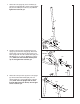
12. Attach the Front Weight Guides (136) to the Right
Top Frame (7) with two M10 x 38mm Screws (82)
a
nd two M10 Washers (116).
R
epeat this step with the Rear Weight Guides
(24).
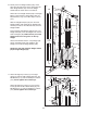
13. Orient the Butterfly Frame (22) as shown. Attach
the Butterfly Frame to the Right Upright (4) with
two M8 x 72mm Bolts (91), two M8 Washers
(117), and two M8 Nylon Locknuts (115).
Do not
tighten the Locknuts yet.
Attach the Butterfly Frame (22) to the Right Top
Frame (7) with two M8 x 80mm Bolts (94), two
M8 Washers (117), and two M8 Nylon Locknuts
(115).
Do not tighten the Locknuts yet.
13
12
7
4
117
1
15
115
115
22
91
116
116
136
82
24
82
7
94
117
117
14
10
94
115
117
117
115
1
15
115
5
84
2
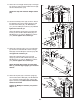
14. Attach the Left Seat Frame (10) to the Left Base
(2) with the two indicated M8 x 75mm Carriage
Bolts (84) and two M8 Nylon Locknuts (115). Do
not tighten the Locknuts yet.
Attach the Left Seat Frame (10) to the Left
Upright (5) with two M8 x 80mm Bolts (94), two
M8 Washers (117), and two M8 Nylon Locknuts
(115). Do not tighten the Locknuts yet.
Attach the Right Seat Frame (9) to the Right
Base (1) and the Right Upright (4) in the same
manner.
15
117
38
20
Handle
89
6
115
15.
Attach the Dip Arm (20) to the Rear Upright (6)
with two M8 x 83mm Bolts (89), two M8 W
ashers
(117), the Rear Upright Plate (38), and two M8
Nylon Locknuts (115).
Make sure the indicated
handle is horizontal.
Tighten the M8 Nylon Locknuts (115) used in
steps 4–15.