Model No. WESY59840 Serial No. Write the serial number in the space above for future reference. Serial Number Decal (under seat) QUESTIONS? As a manufacturer, we are committed to providing complete customer satisfaction. If you have questions, or if there are missing or damaged parts, we will guarantee complete satisfaction through direct assistance from our factory. TO AVOID DELAYS, PLEASE CALL DIRECT TO OUR TOLLFREE CUSTOMER HOT LINE.
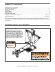
TABLE OF CONTENTS WARNING DECAL PLACEMENT . . . . . . . . . . . . . . . . . . . . . . . . . . . . . . . . . . . . . . . . . . . . . . . . . . . . . . . . . . . . . 2 IMPORTANT PRECAUTIONS . . . . . . . . . . . . . . . . . . . . . . . . . . . . . . . . . . . . . . . . . . . . . . . . . . . . . . . . . . . . . . . . 3 BEFORE YOU BEGIN . . . . . . . . . . . . . . . . . . . . . . . . . . . . . . . . . . . . . . . . . . . . . . . . . . . . . . . . . . . . . . . . . . . . . . 4 ASSEMBLY . . . . . . . . . . . . .
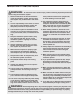
IMPORTANT PRECAUTIONS WARNING: To reduce the risk of serious injury, read the following important precautions before using the resistance system. three positions closest to the upright base, or while standing on the base plate. 1. Read all instructions in this manual before using the resistance system. Use the resistance system only as described in this manual. 13. The resistance system is designed to be used with the included resistance, and the resistance included with a CrossBar by WEIDER™ Power Pak.
BEFORE YOU BEGIN Thank you for selecting the innovative CrossBar by WEIDER™ MAX resistance system. The resistance system offers a selection of stations designed to develop every major muscle group of the body. Whether your goal is to tone your body, build dramatic muscle size and strength, or improve your cardiovascular system, the resistance system will help you to achieve the specific results you want.
ASSEMBLY • Tighten all parts as you assemble them, unless instructed to do otherwise. Make Things Easier for Yourself This manual is designed to ensure that the resistance system can be assembled successfully by most people. However, it is important to realize that the versatile resistance system has many parts and that the assembly process will take time. Most people find that by setting aside plenty of time, assembly will go smoothly.
2. Attach a Wheel (31) to the outside of the Base (1) with an M10 x 78mm Bolt (81), three M10 Washers (75), and an M10 Nylon Locknut (76). Do not overtighten the Locknut; the Wheel must be able to turn easily. 2 76 Attach the other Wheel (not shown) in the same manner. 75 3 23 3 75 11 73 4. Press the Front Leg Foot (27) onto the bottom of the Front Leg (6). Note that the front of the Front Leg Foot is taller than the back.
6. Attach the Lat Tower (4) to the Upright (3) with four M10 x 25mm Button Screws (87), and four M10 Lock Washers (103). 6 Attach the Name Plate (89) to the Lat Tower (4) with two M4 x 16mm Screws (62). 4 62 103 87 89 62 87 103 3 7. Attach two Eyebolts (34) to the Top Frame (10) with two M8 Washers (59) and two M8 Nylon Locknuts (65). Do not overtighten the Locknuts; the Eyebolts must be able to rotate freely.
9. Attach two 8mm Metal Spacers (97), a 60mm Metal Spacer (39), and two Bearing Wheels (46) to one end of the Seat Carriage (12) with an M8 x 104mm Bolt (60) and an M8 Nylon Locknut (65) as shown. Make sure the parts are oriented as shown in the inset drawing; the Seat Knob (not shown) will not engage the Bench Rail (not shown) if they are incorrectly oriented. Do not overtighten the Locknut; the Bearing Wheels must be able to roll easily.
12. Attach a Plastic Foot (53) to the Backrest Frame (15) with an M4 x 16mm Screw (62). 12 Attach the two Guard Plates (17) to the inside of the Backrest Frame (15) with four M4 x 16mm Screws (62). 15 17 13. Attach the Backrest (14) to the Backrest Frame (15) with four 1/4" x 45mm Screws (58). 62 13 53 62 62 17 14 15 58 14. Insert the rod on the Backrest Frame (15) into the slot in the Seat Carriage (12).
16. Locate the Fulcrum (18) on the Lat Tower (4) (see the inset drawing). Slide the Tray (35) onto the rods on the Fulcrum. Make sure the Tray is oriented as shown in the drawing. 16 Set the resistance bars into the Tray (35) in the following order: the 10-pound Removable Resistance Bar (67), the 20-pound Removable Resistance Bar (36), an 80-pound Resistance Bar (95), the 10-pound Center Resistance Bar (44), an 80-pound Resistance Bar (95), and the 40-pound Resistance Bar (96).
20. Wrap the Long Cable (80) under a 90mm Pulley (28) as shown. Attach the Pulley, a Cable Trap (29), an M10 Washer (75), and two Finger Guards (110) to the Upright (3) with an M10 x 127mm Button Bolt (56) and an M10 Nylon Locknut (76). Note: The Bolt will be packaged sepearatly for identification. Make sure the Cable Trap and Finger Guards are oriented as shown. 20 21.
24. Locate the Leg Lever Cable (32), which has two ends that are the same length and a third end that is longer. 24 Route the longest end of the Leg Lever Cable (32) through the hole in the Front Leg (6), and attach it inside of the hole in the Leg Lever (7) with the Short Pin (109) and a cotter Pin (108). 109 25. Attach a 90mm Pulley (28) inside of the hole in the Front Leg (6) with an M10 x 91mm Bolt (90), two 26mm Spacers (52), two M10 Washers (75), and an M10 Nylon Locknut (76).
ADJUSTMENTS This section explains how to adjust the resistance system. See the EXERCISE GUIDELINES on page 17 for important information about how to get the most benefit from your exercise program. Also, refer to the accompanying exercise guide to see the correct form for each exercise. Make sure all parts are properly tightened each time you use the resistance system. Replace worn parts immediately. The resistance system can be cleaned with a damp cloth and a mild, non-abrasive detergent.
ATTACHING THE ACCESSORIES With a high pulley attached to the resistance system (see ATTACHING THE HIGH PULLEYS AND LEG LEVER on page 13), attach a Short Handle (49) to the Short Cable (33) with a Cable Clip (51). 33 51 49 The Short Handles (49), Long Handles (not shown), or Ankle Strap (not shown) can be attached to the Long Cable (80) with a Cable Clip (51). Attach the Curl Bar (8) to the Leg Lever (7) with a Cable Clip.
ADJUSTING THE BACKREST Rod The Backrest (14) can be used in a level position or one of three inclined positions. To use the Backrest in a level position, secure the Seat Carriage (12) to the adjustment hole in the Bench Rail (5) next to the Front Leg (6) (see ADJUSTING THE SEAT on page 13). 15 Slot 13 To use the Backrest (14) in an inclined position, secure the Seat Frame (12) to one of the other three adjustment holes in the Bench Rail (5). Rest the Backrest against the Upright (3).
USING THE REMOVABLE RESISTANCE BARS The Removable Resistance Bars (36, 67) can be used to exercise apart from the resistance system, as shown in the video or on the exercise guide. To remove a Resistance Bar, pull it out of the Tray (35). 67 36 To replace the Removable Resistance Bars (36, 67), slide them into the Tray (35) from the side shown, so that the arrows on the rings point toward the Tray. Make sure the rings are pushed against the Tray.
CABLE DIAGRAM The cable diagram shows the proper routing of the Long Cable (80). Use the diagram to make sure that the cable has been assembled correctly. If the cable has not been correctly routed, the resistance system will not function properly and damage may occur. The numbers show the correct route for the cable.
EXERCISE GUIDELINES THE FOUR BASIC TYPES OF WORKOUTS PERSONALIZING YOUR EXERCISE PROGRAM Muscle Building To increase the size and strength of your muscles, push them close to their maximum capacity. Your muscles will continually adapt and grow as you progressively increase the intensity of your exercise. You can adjust the intensity level of an individual exercise in two ways: • by changing the amount of resistance used • by changing the number of repetitions or sets performed.
Rest for a short period of time after each set. The ideal resting periods are: • Rest for three minutes after each set for a muscle building workout. • Rest for one minute after each set for a toning workout. • Rest for 30 seconds after each set for a weight loss workout. Plan to spend the first couple of weeks familiarizing yourself with the equipment and learning the proper form for each exercise. slowly as you stretch and do not bounce.
PART IDENTIFICATION CHART Refer to the drawings below to identify small parts used in assembly. The number in parentheses below each drawing is the key number of the part, from the PART LIST on the reverse side of this page. Note: Some small parts may have been pre-attached. If a part is not in the parts bag, check to see if it has been pre-attached.
1/4" x 45mm Bolt (58) M10 x 65mm Button Screw (70) M10 x 66mm Carriage Bolt (83) M10 x 72mm Bolt (64) M10 x 78mm Bolt (81) M10 x 91mm Bolt (90) M10 x 103mm Bolt (66) M8 x 104mm Bolt (60) M8 x 114mm Rod (57) M10 x 127mm Button Bolt (56) M10 x 128mm Button Bolt (24) M10 x 147mm Carriage Bolt (73)
PART LIST—Model No. WESY59840 Key No. 1 2 3 4 5 6 7 8 9 10 11 12 13 14 15 16 17 18 19 20 21 22 23 24 25 26 27 28 29 30 31 32 33 34 35 36 37 38 39 40 41 42 43 44 45 46 47 48 49 50 51 52 53 54 55 56 57 58 Qty.
EXPLODED DRAWING—Model No.
ORDERING REPLACEMENT PARTS To order replacement parts, simply call our Customer Service Department toll-free at 1-877-992-5999, Monday through Friday, 6 a.m. until 6 p.m. Mountain Time (excluding holidays).