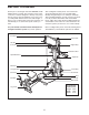
Model No. WESY78734 Serial No. Write the serial number in the space above for future reference. Serial Number Decal (under seat) USER’S MANUAL QUESTIONS? As a manufacturer, we are committed to providing complete customer satisfaction. If you have questions, or if there are missing or damaged parts, we will guarantee complete satisfaction through direct assistance from our factory. TO AVOID DELAYS, PLEASE CALL DIRECT TO OUR TOLLFREE CUSTOMER HOT LINE.
TABLE OF CONTENTS WARNING DECAL PLACEMENT . . . . . . . . . . . . . . . . . . . . . . . . . . . . . . . . . . . . . . . . . . . . . . . . . . . . . . . . . . . . . 3 IMPORTANT PRECAUTIONS . . . . . . . . . . . . . . . . . . . . . . . . . . . . . . . . . . . . . . . . . . . . . . . . . . . . . . . . . . . . . . . . 4 BEFORE YOU BEGIN . . . . . . . . . . . . . . . . . . . . . . . . . . . . . . . . . . . . . . . . . . . . . . . . . . . . . . . . . . . . . . . . . . . . . . 5 ASSEMBLY . . . . . . . . . . . . .
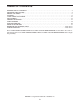
WARNING DECAL PLACEMENT The decals shown here have been placed on the resistance system. If a decal is missing or illegible, please call our Customer Service Department tollfree at 1-877-992-5999, Monday through Friday, 6 a.m. until 6 p.m. Mountain Time, to order a free replacement decal. Apply the decal in the location shown. Keep hands and fingers clear of this area.
IMPORTANT PRECAUTIONS WARNING: To reduce the risk of serious injury, read the following important precautions before using the resistance system. 1. Read all instructions in this manual before using the resistance system. Use the resistance system only as described in this manual. 11. The crossbar on the top frame is not designed to be used for pull-up exercises. Do not hang on the crossbar. 2.
BEFORE YOU BEGIN Thank you for selecting the innovative WEIDER® PLATINUM resistance system. The resistance system offers a selection of stations designed to develop every major muscle group of the body. Whether your goal is to tone your body, build dramatic muscle size and strength, or improve your cardiovascular system, the resistance system will help you to achieve the specific results you want.
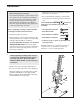
ASSEMBLY • Tighten all parts as you assemble them, unless instructed to do otherwise. Make Things Easier for Yourself This manual is designed to ensure that the resistance system can be assembled successfully by most people. However, it is important to realize that the versatile resistance system has many parts and that the assembly process will take time. Most people find that by setting aside plenty of time, assembly will go smoothly.
2. Insert the connector of the Upper Wire Harness (71) into the socket of the Lower Wire Harness (143). The connector should slide easily into the socket and snap into place. If the connector does not slide easily and snap into place, turn it over and then insert it. 2 6 12 85 Make sure that the connector and wires appear as shown in the inset drawing. IF THE CONNECTOR IS NOT INSERTED PROPERLY, THE CONSOLE MAY BE DAMAGED WHEN THE POWER IS TURNED ON.
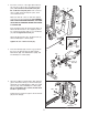
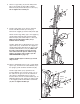
5. Insert the Squat Pin (66) into the Upright (2). 5 Slide the Squat Carriage (19) onto the Upright (2). 2 19 66 6. Attach the Top Frame (37) to the Upright (2) with two M10 x 25mm Button Screws (88), an M10 x 75mm Button Screw (84), three M10 Lock Washers (75), and an M10 Washer (106). 6 88 37 75 84 2 75 106 7. Pull the excess Upper Wire Harness (71) out of the Upright (2). Insert the connector on the Console (67) into the socket on the Upper Wire Harness.
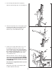
8. Attach a Large Pulley (14) and the Pulley Plate (68) to the Upright (2) with an M12 x 62mm Button Bolt (81) and an M12 Nylon Locknut (13). Do not tighten the Locknut yet. 8 68 13 14 2 81 9. Pull the Upper Cable (121), which is attached inside of the Mech Frame (not shown), up between the Upright (2) and the Pulley Plate (68). 9 Attach another Large Pulley (14) to the Upright (2) and the Pulley Plate (68) with an M12 x 62mm Button Bolt (81) and an M12 Nylon Locknut (13).
11. Insert the Resistance Bar (9) between the Crossbar Guides (15), and center it on the Crossbar Block (not shown). 11 15 70 Press a Pulley Bracket (10) onto the Resistance Bar (9). Screw a 3/8” x 38mm Tension Screw (117) into the Pulley Bracket a couple of turns. Make sure the hexagonal hole in the Screw is on the outside of the Bracket.
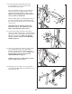
15. Slide a Pad Tube (50) into the Leg Lever (56). Slide two Large Foam Pads (52) onto the Pad Tube. 15 5 Attach the other two Pad Tubes (50) to the Leg Lever (56) and the Leg (5) in the same manner. 50 56 52 50 52 50 16. Insert the rod on the Backrest Frame (32) into the slot in the Seat Carriage (44). Hold the Backrest Frame vertically over the Seat Carriage and slide the rod into the slot, as shown in the inset drawing. 16 32 Rod Slot 44 32 44 17.
UPPER CABLE ADJUSTMENT After completing the assembly of the resistance system, the tension on the Upper Cable (121) will need to be adjusted. Also, the Upper Cable can stretch slightly when it is first used. When this occurs, the upper cable tension will need to be readjusted. Follow the steps below to adjust the upper cable tension. 1. Connect the two Tension Gauges (118, 119) together using the magnet. 1 118 Magnet 119 2.
ADJUSTMENTS This section explains how to adjust the resistance system. See the EXERCISE GUIDELINES on page 21 for important information about how to get the most benefit from your exercise program. Also, see the accompanying exercise guide to see the correct form for each exercise. Make sure all parts are properly tightened each time the resistance system is used. Replace worn parts immediately. The resistance system can be cleaned with a damp cloth and a mild, non-abrasive detergent. Do not use solvents.
ATTACHING THE ACCESSORIES To attach the Lat Bar (82) to the high pulleys, first attach the high pulley to the resistance system (see ATTACHING THE HIGH PULLEYS on page 13). Then, attach the Lat Bar to a High Cable (101) with a Cable Clip (94). Attach the Lat Bar to the other High Cable in the same manner. 101 94 101 The Handles (not shown) and the Ankle Strap (not shown) can be attached to the High Cables (101) or the lower cable (not shown) with Cable Clips (94).
ADJUSTING THE SQUAT ARM 27 To adjust the Squat Arm (20), remove the Squat Knob (27) from Squat Carriage (19). Move the Arm to the low or high position, and reengage the Knob into the Squat Carriage. 19 20 ATTACHING THE SQUAT STATION To use the squat station, first remove the backrest (see ADJUSTING THE BACKREST below). Next, adjust the squat arm to the high position (see ADJUSTING THE SQUAT ARM above). Then, insert a Squat Pin (66) into the correct hole in the Upright (2).
ADJUSTING THE SEAT 45 The Seat (45) can be secured at various positions on the Rail (4). To move the Seat, pull the Seat Knob (48) out as far as it will go and slide the Seat to the desired position. Engage the Seat Knob into an adjustment hole in the Rail. 35 4 To perform row exercises, the hip strap must be attached to the mech cable (see ATTACHING THE ACCESSORIES on page 14), and the Seat Carriage (44) must be able to roll along the Rail (4).
CONSOLE OPERATION FEATURES OF THE CONSOLE Console PLUGGING IN THE RESISTANCE SYSTEM Plug the indicated end of the Transformer (72) into the Back Mech Cover (8). Plug the other end of the Transformer into a 8 120-volt outlet. All 72 indicators and displays on the console will flash once; the console will then be ready for use. The motor may be heard while the resistance system calibrates itself. Important: Always plug in the transformer when using the resistance system. MANUAL OPERATION 1.
Note: The resistance system uses progressive resistance. As the resistance bar begins to bend, the amount of resistance will increase gradually. As the bar bends further, the resistance will increase rapidly, up to 340 pounds. 3. Row for five minutes to warm up. When a program is selected, the words CARDIO ROW will appear in the main display. To warm up, perform the cardio row exercise while the main display counts down from 5 minutes. 3.
CABLE DIAGRAM The cable diagram shows the proper routing of the Upper Cable (121). Use the diagram to make sure that the cable has been assembled correctly. If the cable has not been correctly routed, the resistance system will not function properly and damage may occur. The numbers show the correct route for the cable. Make sure that the ends of the cable do not wrap around each other between positions 1 and 2, and 5 and 6.
TROUBLESHOOTING CLEANING THE BAR GUIDES Over time, dust may build up on the Crossbar Guides (15), causing a squeaking noise as the resistance system is used. If this occurs, wipe off the Crossbar Guides with a damp cloth and a mild, non-abrasive detergent. Do not use solvents. 15 ADJUSTING THE RESISTANCE When the resistance setting changes, the motor will be heard. To prevent damage to the motor, do not pull any of the cables while the resistance setting is changing.
EXERCISE GUIDELINES THE FOUR BASIC TYPES OF WORKOUTS PERSONALIZING YOUR EXERCISE PROGRAM Muscle Building To increase the size and strength of your muscles, push them close to their maximum capacity. Your muscles will continually adapt and grow as you progressively increase the intensity of your exercise. You can adjust the intensity level of an individual exercise in two ways: • by changing the amount of resistance used • by changing the number of repetitions or sets performed.
slowly as you stretch and do not bounce. Ease into each stretch gradually and go only as far as you can without strain. Stretching at the end of each workout is an effective way to increase flexibility. Rest for a short period of time after each set. The ideal resting periods are: • Rest for three minutes after each set for a muscle building workout. • Rest for one minute after each set for a toning workout. • Rest for 30 seconds after each set for a weight loss workout.
EXERCISE MONDAY WEIGHT SETS REPS WEIGHT SETS REPS WEIGHT SETS REPS Date: / / AEROBIC EXERCISE TUESDAY Date: / / WEDNESDAY EXERCISE Date: / / THURSDAY AEROBIC EXERCISE Date: / / EXERCISE FRIDAY Date: / / Make photocopies of this page for scheduling and recording your workouts.
REMOVE THIS PART IDENTIFICATION CHART AND PART LIST/ EXPLODED DRAWING. SAVE THIS PART IDENTIFICATION CHART AND PART LIST/EXPLODED DRAWING FOR FUTURE REFERENCE. PART IDENTIFICATION CHART—Model No.
PART LIST—Model No. WESY78734 Key No. Qty.
53 21 52 56 50 51 42 43 51 40 62 57 50 51 51 104 106 102 61 55 103 21 41 21 103 40 62 60 100 92 113 108 60 5 61 106 113 58 52 41 45 82 46 102 63 106 106 48 49 103 106 26 115 104 26 104 101 40 93 75 44 103 47 37 115 103 41 59 103 93 39 26 104 115 101 103 38 103 100 80 106 21 103 39 38 75 88 1 4 34 36 64 99 35 103 116 103 116 36 106 106 103 64 103 65 103 77 106 105 32 107 65 81 3 103 30 110 106 103 106 67
ORDERING REPLACEMENT PARTS To order replacement parts, simply call our Customer Service Department toll-free at 1-877-992-5999, Monday through Friday, 6 a.m. until 6 p.m. Mountain Time (excluding holidays).