
User manual
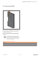
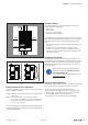
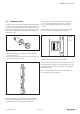

35 mm
1.38"
40 mm
1.57"
40 mm
1.57"
20 mm
0.97"
20 mm
0.97"
Minimum distances with vertical installation
1.18"
30 mm
10
mm
0.39"
Minimumdistancetoswitchcabinetdoor(with/withoutswivelmarker)
Example calculation for space requirements
The space requirements for a u-remote station with n mod-
ules is calculated as follows:
Height: 120mm + 2 x 40mm (distances at top and bottom)
=200mm
Width: 8mm (end bracket) + 52mm (bus coupler) +
nx11.5mm (nmodules) + 11.5mm (end plate and
end bracket) + 2x20mm (distances to the sides)
=111.5 + nx11.5mm
For vertical installation interchange height and width. When
calculating the width, 4.5mm for the must be added for the
end bracket MEW35/1.
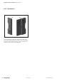
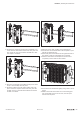
Installation sequence
A u-remote station may only be installed in this sequence
(starting from the left/bottom):
– End bracket
– Bus coupler
– Up to 64 active modules
– End plate and end bracket
If the station has already been congured, please proceed to
the corresponding installation drawing. If you are conguring
the station yourself, please observe the following instruc-
tions:
– Observe the maximum current carrying capacity (see sec-
tion 4.5)!
– Furthermore, the modules may be arranged in any
sequence. In order to configure the station as clearly as
possible, we recommend arranging the modules accord-
ing to their function.
ArrangementofSILmodules
A PF-O-xDI-SIL module can be positioned anywhere in the u-
remote-station. All of the following output modules up to the
next PF-O module are safely disconnected (safety segment).
Multiple PF-O-SIL modules / safety segments can be set up
in a single station.
When using u-remote PF-O-xDI-SIL modules,
please also observe the Modules for Func-
tional Safety Manual.
The manual is available to download from the
Weidmüller website.
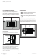
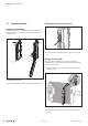
Preparationandtherequiredtool
The DIN rail must already be installed. To mechanically install
the u-remote station, you will need a 3-mm screwdriver.
▶ Lay out the modules in the intended sequence.
▶ Check whether the DIN rail feet can be moved on both
end brackets. If necessary, loosen the mounting screw
until the DIN rail feet can be moved freely.
▶ If not done yet, fit an earth terminal to the DIN rail.
Installation | Preparations for assembly
235Manual u-remote1432790000/03/02.2014