
User manual

ANNEX
A-3Manual u-remote1432790000/03/02.2014
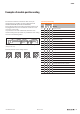
The incorrect insertion of electronic units can be pre-
vented if the base modules are given coding elements
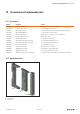
COBHZCH20MBK (Order No.1429560000)
Three coding sockets each with four possible positions can
be plugged into every base module. This results in a maxi-
mum of 4
3
or 64 codes.
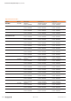
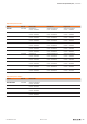
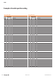
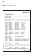
It is practical to use either functionally oriented or slot-
oriented coding. Example codes are provided for each coding
scheme in the following tables.
1 2 3
Base module with three coding places and coding sockets plugged
(Example code 013)
Possible positions of the coding sockets:
0 1
3 2
0 1
3 2
0 1
3 2
0 1
3 2
0 1 2 3
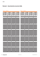
Functionally-orientedcoding
Code
Codingposition
Meaning1 2 3
01
0 0 0 4 digital inputs (4DI)
02
0 0 1 8 digital inputs (8DI)
03
0 0 2 16 digital inputs (16DI)
10
0 2 1 4 digital outputs (4DO)
11
0 2 2 8 digital outputs (8DO)
12
0 2 3 16 digital outputs (16DO)
40
2 1 3 1-channel counter (1CNT)
41
2 2 0 2-channel counter (2CNT)
13
0 3 0 2-channel PWM module (2PWM)
20
1 0 3 4 analogue inputs (4AI)
21
1 1 0 8 analogue inputs (8AI)
30
1 3 1 4 analogue outputs (4AO)
22
1 1 1 4 temperature inputs (4AI-X-DIAG)
50
3 0 1 Power-feed module input (PF-I)
51
3 0 2 Power-feed module output (PF-O)
52
3 0 3 Power-feed module output 1DI SIL (1DI-SIL)
53
3 1 0 Power-feed module output 2DI SIL (2DI-X-SIL)
60
3 2 3 Potential distributor +
61
3 3 0 Potential distributor –
62
3 3 1 Potential distributor FE (16AUX-FE)
63
3 3 2 Empty slot module (ES)
Examplesofmodulepositioncoding