
User manual


Detaileddescriptionsoftheeld-buscoupler | Probus DP eld-bus coupler UR20-FBC-PB-DP
37Manual u-remote1432790000/03/02.2014
5 Detaileddescriptionsoftheeld-buscoupler
5.1 ProbusDPeld-buscoupler
UR20-FBC-PB-DP
The UR20-FBC-PB-DP eld-bus coupler is a PROFIBUS-DP
participant certied by the PROFIBUS user organisation. The
coupler is the head module for the u-remote system bus, to
which up to 64 active u-remote modules can be connected.
The PROFIBUS-DP coupler has a Sub-D socket and supports
all services in accordance with the DP-V1 specication.
The coupler can be activated with a system-independent
web server application via the USB service interface. In addi-
tion, all information, such as diagnostics, status values and
parameters, can be exported and all connected modules can
be simulated or forced.
The station's main power supply is integrated in the coupler.
Power is supplied via two 4-pole connectors, separated into
the input and output current paths.
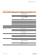
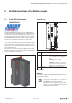
Field-buscouplerUR20-FBC-PB-DP(OrderNo.1334870000)
Status indicators
PWR
SF
BF
MT
PB-DP
1
2
3
4
1
2
3
4
3
4
LEDstatusindicatorsUR20-FBC-PB-DP
PWR
Power LED Green: Supply voltage
SF
Collective error Red: Conguration error, or error in the coupler,
or error in a module, or there is a new diagnostic
report
Redashing: Station in Force mode
BF
Bus failure Red: No connection to the eld-bus
Redashing: Conguration error, no connection
to the control unit, or error in the parameter set or
slave address error or rmware update is running
MT
Maintenance Yellow: Error on the system bus or eld-bus
LED status indicators
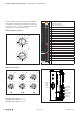
Addressing
The eld-bus coupler on the PROFIBUS-DP is addressed via
the two rotary switches.
A maximum of 125 addresses (1 to 125) can
be assigned. Each address may be assigned
only once in the overall bus structure.
Addresses 1 and 2 are generally used by the
control systems. Bus addresses 000 plus 126
and higher may not be used!