
User manual

Detailed descriptions of I/O modules | Digital counter module UR20-1CNT-100-1DO
138 1432790000/03/02.2014Manual u-remote
Counter functions
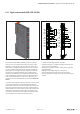
Overview
As essential conditions to start counting the signal mode
needs to be parametrized and a rising ank at the bit “Set
SW gate” of the control word is required.
Counting can be carried out up or down, during which time
the following functions are available:
– 1-time counting, e.g. for counting products up to a maxi-
mum limit
– Continuous counting, e.g. for detecting the position with
an incremental encoder
– Periodic counting, e.g. repeated identical pick-and-place
operations
Through parametrization, a counting range with a start and
stop value can be dened in the “1-time counting” and “peri-
odic counting” operating modes.
Parameterizable additional functions are available with the
counter in the form of the gate function, comparator, hyster-
esis and process alarm.
Primary counting direction
A primary counting direction can be predetermined for the
counter through parametrizing.
When “none” is selected, the entire counting range is avail-
able.
Countingrange
Limits Validrangeofvalues
Lower count limit –2 147 483 648 (–2
31
)
Upper count limit +2 147 483 647 (2
31
– 1)
Primary counting direction up
The counting range is limited at the top. Starting at 0 or the
load value, the counter counts to the parametrized end value
-1 and is reset to the load value with the next encoder pulse.
Primary counting direction down
The counting range is limited at the bottom. Starting from
a parametrized start or load value, the counter counts until
the parametrized end value +1 and is reset to the start value
with the next encoder input.
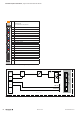
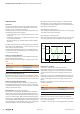
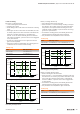
Gate function cancelling / interrupting
The counter is activated and deactivated using an internal
gate (I-gate). If the hardware gate (HW gatephysical input
“Gate”) is deactivated in parameters the internal gate is iden-
tical to the software gate. With activated hardware gate the
internal gate is a logic AND connection of hardware gate and
software gate. When the HW gate is released, the gate func-
tions operate only on the HW gate. In this case, opening and
closing the SW gate has only an interrupting effect.
The software gate is activated using a 0-1 edge at the bit
“Set SW gate” in the control word. It is deactivated with a
0-1 edge at the bit “Reset SW gate” in the control word (see
table “Process data outputs”).
Cancelling the counting process
After closing the gate and a new gate start, the counting pro-
cess starts over from the load value.
Interrupting the counting process
After closing the gate and a new gate start, the counting pro-
cess starts again from the last updated counter reading.
Upper
count limit
Lower
count limit
Load value
Gate start Gate stop Time
Counter state
0
Overrun
Underrun
Overviewofgatefunctions
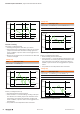
Continuous counting
In this case, counting starts with the load value.
If the upper count limit is reached during up-counting, an
additional counting pulse in the positive direction leads to
a jump to the lower count limit. Counting continues from
there.
If the lower count limit is reached during down-counting, an
additional counting pulse in the negative direction leads to
a jump to the upper count limit. Counting continues from
there.
Because of the register size, the count limits are xed and
cannot be changed.
Countingrange
Limits Validrangeofvalues
Lower count limit –2 147 483 648 (–2
31
)
Upper count limit +2 147 483 647 (2
31
– 1)
The status bits “Overow performed” and “Underow per-
formed” are set in the case of an overow or underow.
They remain set until they are reset with the bit “Reset status
bits” in the control word.
In addition, a process alarm can be triggered if it is provided.