
User manual


System overview | General description of I/O modules
13Manual u-remote1432790000/03/02.2014
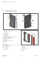
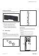
The connection frame can take up to four connectors,
and four conductors can be connected to each connector.
“PUSH IN” technology allows for ne-wired conductors with
crimped wire-end ferrules or ultrasonically welded conduc-
tors, each with a maximum cross-section of 1.5mm², to be
inserted easily through the opening in the clamping terminal
without having to use tools. To insert ne-wired conductors
without wire-end ferrules, the pusher must be pressed in
with a screwdriver.
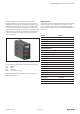
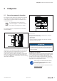
Connectors with four conductor connectors
The pushers are colour-coded for the following connections:
Grey Signal
Blue GND
Red 24VDC
Green Functional earth (FE)
Detailed descriptions of the individual module types are
available in Chapter6.
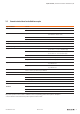
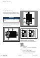
Cable protection
The modules listed in the following table do not have a fused
sensor/activator power supply. Here, all cables to the con-
nected sensors/actuators must be fused corresponding to
their conductor cross-sections (as per Standard EN60204-1,
section12).
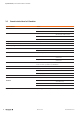
Modules Order No.
Digitalinputmodules
UR20-4DI-P 1315170000
UR20-8DI-P-3W 1394400000
UR20-2DI-P-TS 1460140000
UR20-4DI-P-TS 1460150000
Digitaloutputmodules
UR20-4DO-P 1315220000
UR20-4DO-P-2A 1315230000
UR20-4DO-PN-2A 1394420000
Analogueinputmodules
UR20-4AI-UI-16 1315620000
UR20-4AI-UI-12 1394390000
Functional modules
UR20-2PWM-PN-0.5A 1315600000
UR20-2PWM-PN-2A 1315610000
UR20-1CNT-100-1DO 1315570000
UR20-2CNT-100 1315590000
Potentialdistributionmodules
UR20-16AUX-I 1334770000
UR20-16AUX-O 1334780000
UR20-16AUX-GND-I 1334800000
UR20-16AUX-GND-O 1334810000