
User manual
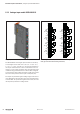
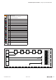


Detailed descriptions of I/O modules | Analogue input module UR20-4AI-UI-16
174 1432790000/03/02.2014Manual u-remote
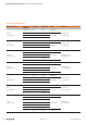
TechnicaldataUR20-4AI-UI-16(OrderNo.1315620000)
System data
Data
Process, parameter and diagnostic data depend on the coupler used,
see the table in Section 4.10.
Interface
u-remote system bus
System bus transfer rate
48 Mbps
Inputs
Number
4
Input values
1. Voltage (0 ... 5V, ±5V, 0 ... 10V, ±10V, 1 ... 5V, 2 ... 10V)
2. Current (0 ... 20mA, 4 ... 20mA)
Resolution
16 bits
Accuracy
±0.1 % max.
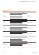
±50ppm/K max.
max. –10mV/A
at 25°C
Temperature coefcient
additional inaccuracy in the voltage mode due to
sensor power supply current
Sensor supply
max. 2A per plug, total max. 8A
Sensor connection
2-wire, 3-wire, 3-wire + FE
Conversion time
1ms
Internal resistance
U: 100kΩ; I: 41.2Ω
Reverse polarity protection
yes
Short-circuit-proof
yes
Response time of the protective circuit
< 50ms
Modulediagnosis
yes
Individualchanneldiagnosis
no
Supply
Supplyvoltage
24V DC +20 %/-15 %
Currentconsumption(I
IN
inthepowersegmentofthefield-bus
coupler),typ.
8mA
Currentconsumption(I
IN
intherespectivepowersegment)
25mA + sensor feed Input current path
General data
Weight
89g
Foradditionalgeneraldata,seeSection3.4
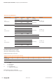
Overview of the editable parameters UR20-4AI-UI-16
Channel Description Options(Value) Default value
Frequency suppression disabled (0) / 50Hz (1) / 60Hz (2) / Average over 16 values (3) disabled
0 ... 3 Data format S5 Data format (0) / S7 Data format (1) S7 Data format
0 ... 3 Measurement range
0 to 20 mA (0) / 4 to 20 mA (1) / 0V to 10V (2) / -10 to 10V (3) /
0 to 5V (4) / -5 to 5V (5) / 1 to 5V (6) / 2 to 10V (7) /disabled (8)
disabled