
User manual


1.
2.
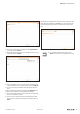
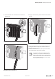
UnlockingthelastI/Omodule
▶ Slide the module on the DIN rail approximately 5cm to
the right, push it onto the DIN rail and click the release
lever into place.
▶ Repeat the aforementioned step for all other modules
which are located to the right of the module being
replaced: release, slide to the right and click in once
again.
▶ Remove the connector frame of the module to be
replaced as described in the “Removing the connector
frame” section.
▶ Open the release lever for the module to be removed.
1.
2.
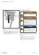
UnlockingtheI/Omoduletobereplaced
▶ Slide the module to the right and remove it from the DIN
rail.
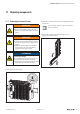
▶ Position the new module with its closed release lever on
the DIN rail so that it clicks audibly into place.
▶ Slide the module to the left until it audibly clicks into
place against the neighbouring module.
▶ Return the modules that were slid away back into their
original position: slide the modules to the left so that they
audibly click into place on the new module.
After all the modules have been moved, make
sure that they have all been clicked securely
into place on the DIN rail!
▶ Reassemble the end plate and end bracket.
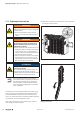
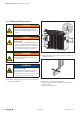
▶ Place the connector frame in a 90° position from below
into the guideway of the base module on the new mod-
ule.
The connector frame can only be inserted in
this 90° position!
90°
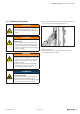
Insertingtheconnectorframe
▶ Swivel the connector frame upwards until it clicks into
place.
Replacingcomponents | Replacing an I/O module
277Manual u-remote1432790000/03/02.2014